Diagnosing and attempting to fix a Yamaha DX100 – Part 3
At the end of part 1, I’ve established that the basics all seem ok (PCB, interconnections, power) and that basic digital logic stuff is happening.
In part 2 I checked the ROM, reflowed a number of the solder joints, and started to look at the connectors between the main PCB and the LCD, but still with no luck.
Now I’m finally getting around to looking properly at those data signals to see what my next steps might be.
Oh and nope, still not fixed. Sorry.
Warning! I am not an electronics person. I strongly recommend that you don’t base your own attempts at fixing a beloved vintage synth on anything I’ve said here. I was given this synth rather than it being sent it to a recycling centre so this is a low-risk learning activity for me. I am not responsible for any damage to expensive or irreplaceable electronic musical instruments! There are plenty of places to take something for a proper repair 🙂
If you are new to microcontrollers and electronics, see the Getting Started pages.
Replacing the LCD – Continued
In part 2 I thought that it would be worth seeing if I could replace the LCD with an alternative, seeing as it appeared to be just a common HD44780 based display, but the connector used was giving me trouble.
In the end I just took the plastic shrouds off some Dupont style jumper wires and poked them directly into the connector on the PCB.
This finally gives me a way into some of the control signals and data lines on the main bus. First things first, I connected up a replacement display. Usefully the pinout of this connector matches exactly the pinout of a LCD1602 display.
The only additional connections required are an extra +5V/GND for the backlight (marked as “K” and “A” on my display). All the other connections match as shown by the schematic.
Hooking up an oscilloscope as follows:
- Yellow = E = LCD Enable pin (decoded from A10-15=0; A13=1)
- Blue = R/W (low = write)
- Purple = RS = register select (maps onto A0 on the address bus)
- Darker blue = D0
and triggering off the enable pin gives me the following trace:
The darker blue line is D0 and as can be seen – it is basically all over the place. It definitely looks like something is breaking the data lines, so the question now is what. I also checked D1-D7 and they all look pretty similar.
From my previous experiments the fact that I can read the ROM successfully, and now have replaced the LCD implies one of the other devices. So I think that leaves the following options:
- The CPU itself
- RAM
- A/D
- OPP – the Yamaha FM tone generator itself
But as all these are soldered down, it makes the next step a little tricky.
I’ve triggered the scope of the various CS/OE lines for the RAM, ADC and OPP and checked the local equivalent of D0 and the pattern seems the same everywhere.
Interestingly I don’t ever see a CS/OE line for the ADC or OPP – but then if it is failing to boot then the CPU will never get around to trying to access either of those I’d imagine.
By the way, on startup, there are there points where the LCD “E”nable pin is accessed. Two single instances, and then a large block as shown below.
Removing the ROM
Just out of interest I thought it was worth seeing what the signals looked like with the ROM removed (seeing as it is socketed and easy to remove). I triggered of the CE for one of the RAM chips and checked the signals.
The RAM isn’t accessed as much, but then with no ROM I don’t know what the CPU would be doing anyway…
But when it is, D0 (dark blue again in the trace below) looks a lot more like a sensible digital signal to me.
So now I’m thinking I really ought to eliminate the idea of a problem ROM chip before desoldering any of the RAM to test that…
Aside: at one point, when just monitoring the data signal, I got a much cleaner signal, but very definitely appearing to show three distinct states, which again reinforces the fact that something, somewhere is trashing over the data lines…
Replacing the ROM
As discussed last time, the DX100 uses a 27C256 style ROM which isn’t quite the same pinout as the more common 28C256 EEPROM that can be found relatively easily these days. However there is also a 29C256 which does have essentially the same pinout as the 27C256.
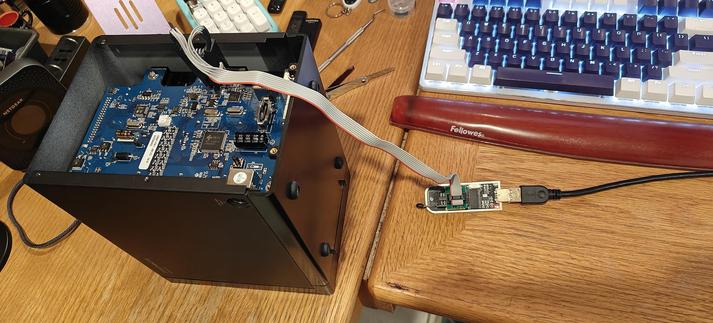
I happen to have some, but I don’t know if they are any good! I also have my Arduino EEPROM Reader but I’ve never tried to write with it and certainly not tried to do anything with a 29C256.
So this might have to wait for another day now as getting a replacement ROM might turn into a mini side-project in its own right.
If I do give that a go, I’ll come back and update this post.
Further Thoughts
I feel like I’ve made a little more progress in appearing to have eliminated the LCD as a source of the issue.
I don’t feel like the ROM is the problem, as I was able to successfully read it with my programmer, but on the basis that it can be swapped out without anything drastic like desoldering chips, I really ought to try that before taking a soldering iron to the RAM chips…
Of course, if you spot any other options do feel free to let me know.
Kevin
#dx100 #eeprom #lcd1602