I’m continuing my series of experiments with the ESP32 by considering how I might use the twin DACs onboard the WROOM module as a Lo-Fi, 8-bit envelope generator. I’ve not looked at envelope generation before, so this is a good excuse to see what it is all about.
Important Note: This is NOT an envelope generator circuit or standalone device at present. It just outputs the waveform to the DAC. There is no electronics here that would make that a usable signal in any kind of controlling manner at present. This is mostly thinking about the code to produce the waveforms.
In short, don’t hook this up to anything else unless you really know what you are doing (unlike me).
Warning! I strongly recommend using old or second hand equipment for your experiments. I am not responsible for any damage to expensive instruments!
These are the key tutorials for the main concepts used in this project:
If you are new to microcontrollers, see the Getting Started pages.
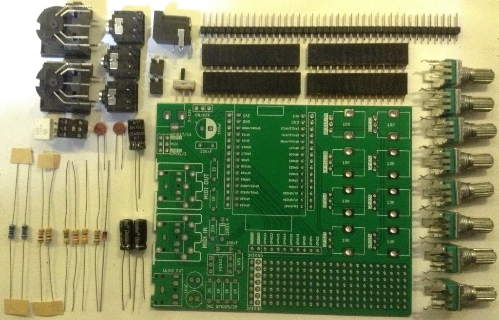
Parts list
- ESP32 WROOM DevKit
- 4x or 8x 10kΩ potentiometers
- 2x 1kΩ resistors
- 2x push/toggle switches
- Breadboard and jumper wires
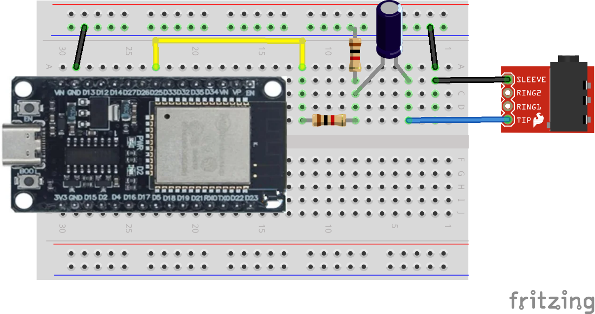
The Circuit
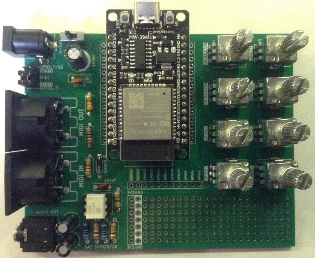
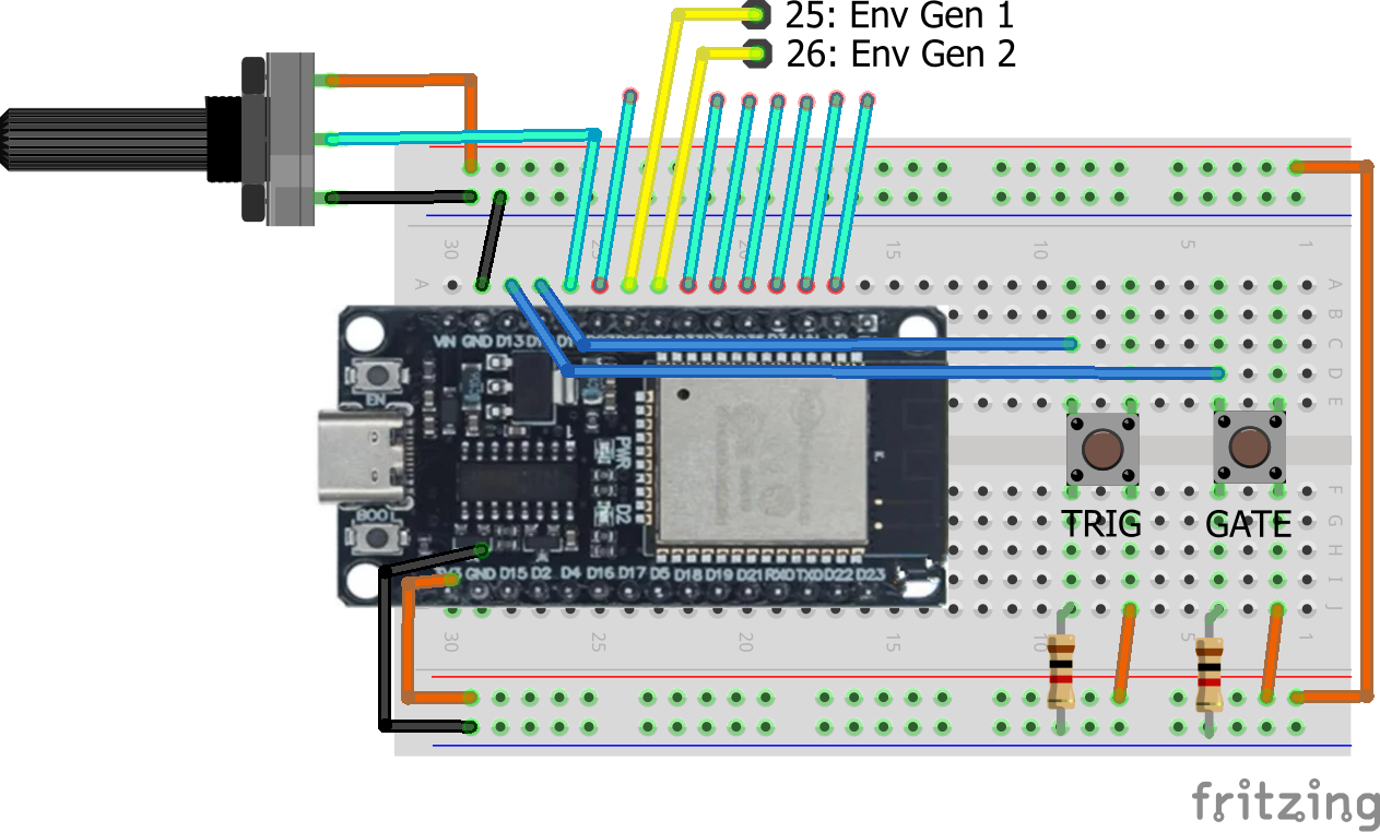
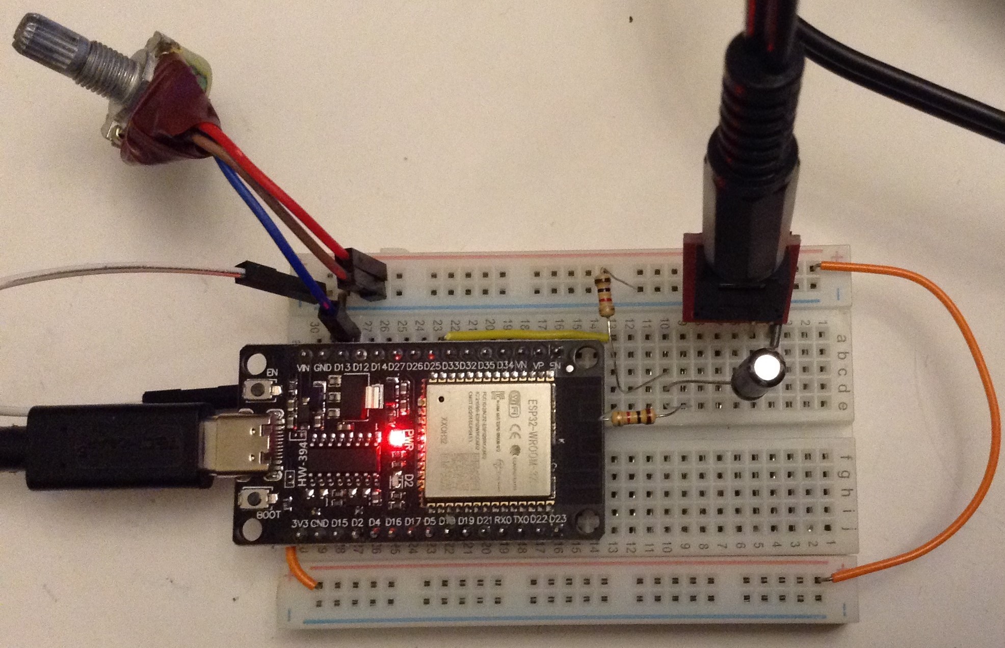
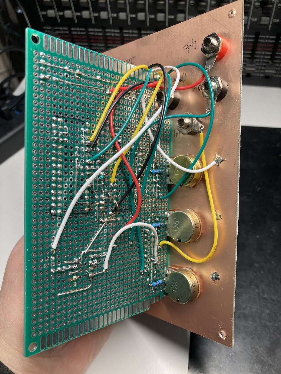
I’ve ended up wiring potentiometers to eight analog inputs, buttons to two digital inputs and put my oscilloscope on each of the DACs to see the output.
The potentiometers are wired in the usual VCC-signal-GND manner (although only one is shown above). The buttons are pulled down as the signals are meant to be active HIGH signals.
The Trigger input is a pulse indicating when a key would be pressed and signifying the start of the envelope generation. When triggered the Attack stage of the envelope will begin immediately followed by the Delay phase. The Gate input is held and meant to indicate while the key is pressed and when it is released. Whilst on, the envelope will remain in the Sustain phase. On removal of the Gate signal the Release stage of the envelope will start.
Note that the plan is for the Trigger to allow retriggering of the envelope at any time and that for removal of the Gate can also happen at any time and start Release. It is also quite possible for there to be several triggers whilst the gate is still active.
It is also possible for the trigger and gate pin to be the same in which case trigger happens on the rising edge along with gate ON and gate OFF will happen on the falling edge.
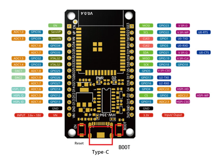
Here is the full GPIO list for this experiment.
GPIO 25DAC – Envelope 1 outGPIO 26DAC – Envelope 2 outGPIO 12Trigger inputGPIO 13Gate inputGPIO 14Env 1 AttackGPIO 27Env 1 DelayGPIO 33Env 1 SustainGPIO 32Env 1 ReleaseGPIO 35Env 2 AttackGPIO 34Env 2 DelayGPIO 39Env 2 SustainGPIO 36Env 2 Release3V3Pot VCCGNDPot GND
I’ve used the same GATE and TRIGGER signals for both envelope generators, but it would be quite happy with four independent inputs.
Everything here is working with 3V3 logic levels, including the envelope voltages produced.
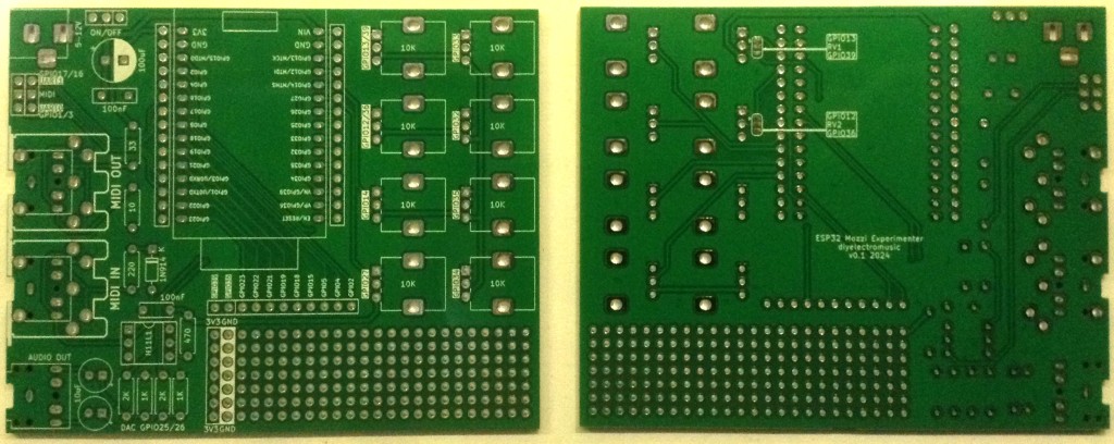
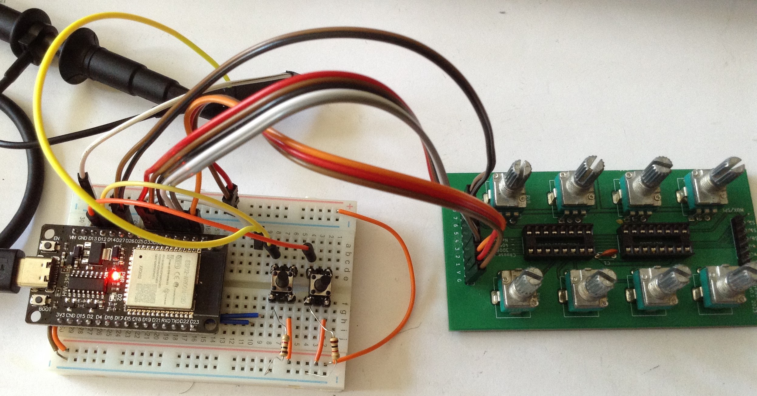
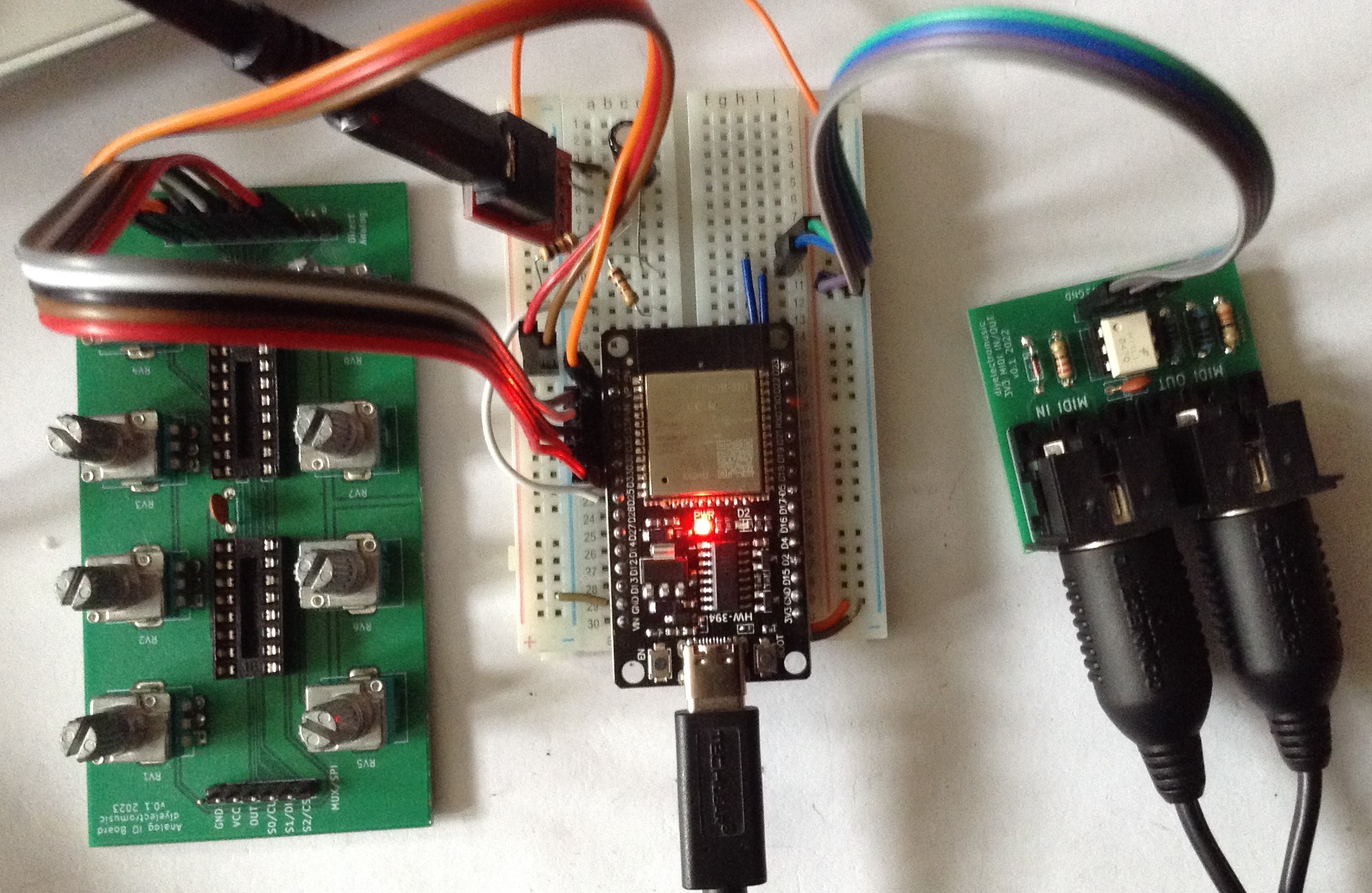
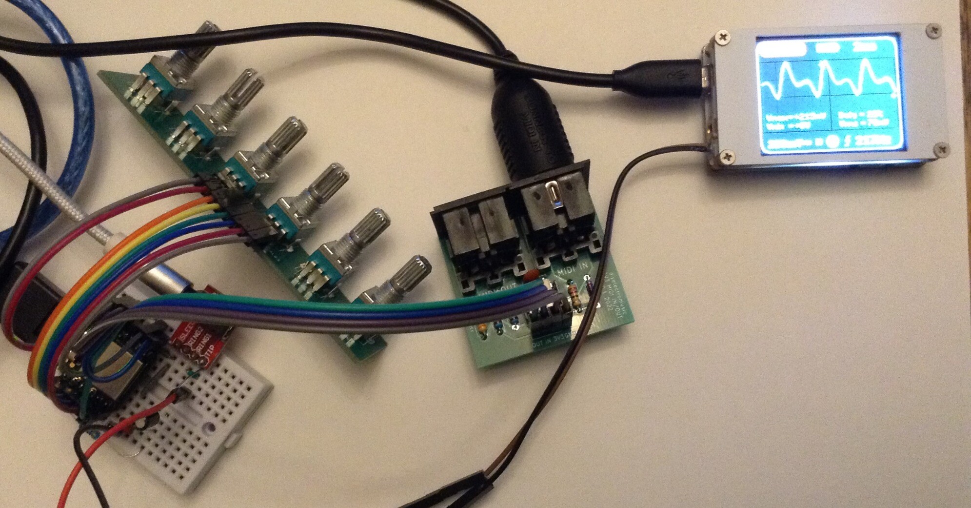
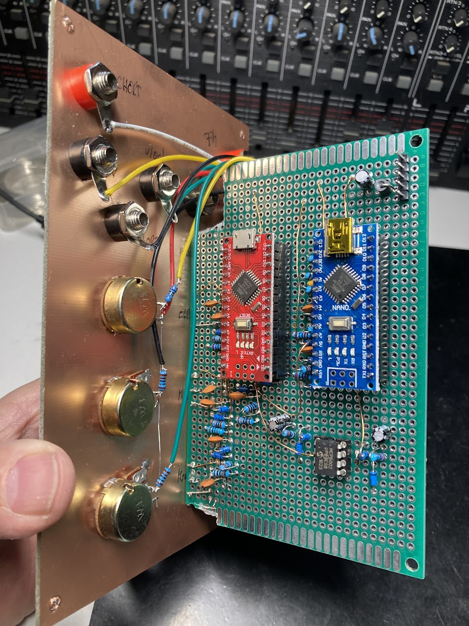
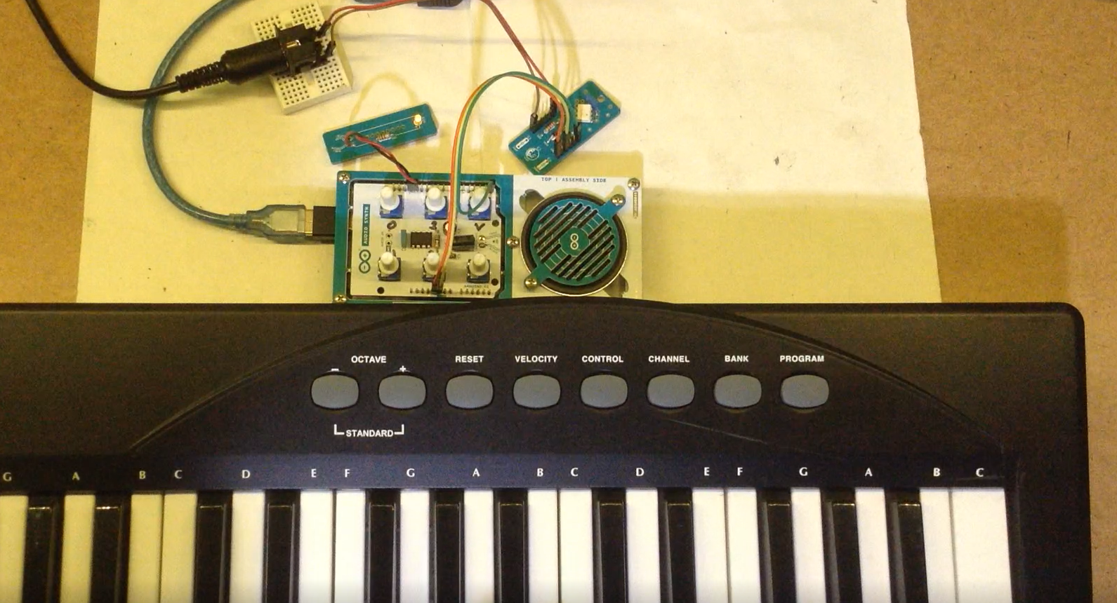
In the photo below I’ve simplified my wiring by using my Analog IO Board PCB to give me eight potentiometers directly wired into the ESP32.
Envelopes in Mozzi
I’ve already used envelopes in my experiments with ESP32 and Mozzi, but they are applied in software to modulate the amplitude of the Mozzi synthesized output. And really, if using a microcontroller for synthesis this is the natural way to do things.
By way of an example, in Mozzi, envelopes are created on startup, have their parameters changed as part of the control loop, are triggered on and off usually in response to note events, and then have each instantaneous value calculated as part of the audio loop an applied to the sample value.
The essence of their use in Mozzi is as follows:
#include <ADSR.h>

ADSR <CONTROL_RATE, AUDIO_RATE> envelope;

void HandleNoteOn(byte channel, byte note, byte velocity) {
  envelope.noteOn();
}

void HandleNoteOff(byte channel, byte note, byte velocity) {
  envelope.noteOff();
}

void setup () {
  envelope.setADLevels(ADSR_ALVL, ADSR_DLVL);
  envelope.setTimes(ADSR_A, ADSR_D, ADSR_S, ADSR_R);
}

void updateControl(){
  IF ADSR values have changed THEN
    call setADLevels and setTimes again as required
}

AudioOutput_t updateAudio(){
  Calculate new 8-bit sample
  return MonoOutput::from16Bit(envelope.next() * sample);
}
All that would be required to get this to output just the envelope would be to change the return statement in updateAudio to return the envelope value directly.
AudioOutput_t updateAudio(){
  return MonoOutput::from8Bit(envelope.next());
}
There are several more example sketches in Examples->Mozzi->07.Envelopes.
There are several issues with this approach that stop me using this for what I want to do:
- This only supports one output. I might be able to configure two envelopes and get one output on the “left” channel and one on the “right” channel, which I think then map onto the two DACS…
- I want to integrate this with some of my ESP32 PWM messing around too, which isn’t easy when Mozzi is determining all the outputs. There is an option to use a user-defined function for the output, but at this point I’m doing a lot more myself anyway…
And anyway, I wanted to work out how an envelope generator could be implemented myself. So I didn’t use Mozzi and got to work on my own implementation.
DIY Envelope Generation using Timers
I had an initial look around at any existing envelope generator implementations for Arduino, having a look at both ADSRduino and the Mozzi ADSR implementation.
In the end I opted for a simpler design of my own, deciding to manage the ADSR as a state machine in code with calculations for how much the envelope level needs to change per tick of a timer. I’m just implementing simple linear updates for each stage.
Setting up the timer is the same as for PWM, but this time I’m using a 100kHz timer with an alarm every 10kHz. This gives me a 0.1mS “tick” which is more than adequate for generating an envelope.
I’ve opted to map the potentiometers onto the ADSR parameters as follows:
- ADR are mapped using: 1 + potval * 2.
- S is mapped directly to a value in the 0..255 range, reflecting the 8-bit DAC output.
The time values are in units of 0.1mS so can specify a duration for any of the three stages between 0.1 and 819.1 mS. For pragmatic reasons, when using these values in calculations, I always add 1 so I don’t ever have a divide by zero (which causes the ESP32 to reset).
All values relating to a level are in 8.8 fixed point format, so are essentially 256 times larger than they need to be to give more accuracy in calculations.
The ADSR state machine has the following functionality:
Idle:
  Do nothing

Trigger:
  Start Attack

Attack:
  Increase level to maximum from current level one step at a time
  IF level reaches maximum:
    Move to Delay

Delay:
  Decrease level to sustain level one step at a time
  IF level reaches sustain level:
    Move to Sustain

Sustain:
  Stay at same level while Gate is ON
  IF Gate is OFF
    Move to Release

Release:
  Decrease level down to 0 one step at a time
  IF level reaches zero
    Move back to Idle
For each stage I maintain a step value, which is how much the level has to change for that specific step. This is calculated as follows:
Num of Steps for this stage = Time of the stage / SAMPLE RATE
Usefully, if I’m measuring the time of the stage in mS then I can use a SAMPLE RATE in kHz and the calculation still works. So the step increment itself can be found by:
Step increment = (Required end level – Starting level) / Num steps
Step increments can be positive or negative of course depending on whether the output is rising or falling.
As already mentioned I’m using 8.8 fixed point arithmetic for the levels. The biggest concern was watching out for automatic wrapping of the 16-bit values whilst performing calculations, so I’ve removed that as a possibility by using signed, 32-bit values for the step increment and stored level.
All the parameters associated with an envelope are stored in a structure:
struct adsrEnv_s {
  int32_t  env_l;
  int32_t  steps;
  uint16_t attack_ms;
  uint16_t attack_l;
  uint16_t delay_ms;
  uint16_t sustain_l;
  uint16_t release_ms;
  bool gate;
  adsr_t state;
} env[NUM_DAC_PINS];
And there are a number of functions for manipulating the envelope. This is the point where really I ought to be branching over into “proper” C++ and making this an object, but I’ve stuck with C, structures and arrays for now.
The final implementation has a few extra steps in the state machine corresponding to the transitions between stages. This just makes calculating the new step values clearer at the expense of adding an extra timer “tick”‘s worth of processing time to each stage.
Two complications come from how the gate and trigger need to be handled.
The gate has to be checked in each of the stages and if the gate goes to OFF then the state needs to switch over to Release.
The trigger needs to come externally to the main state machine, but in order to ensure I’m not attempting to update variables at the same time that that they are being manipulated by the interrupt-driven state machine function, the trigger just updates the state to a “trigger” state so that on the next tick, the state machine will update itself.
The full set of states recognised now stands as follows (stored roughly in the order they progress through):
// ADSR state machine
enum adsr_t {
  adsrIdle=0,
  adsrTrigger,
  toAttack,
  adsrAttack,
  toDelay,
  adsrDelay,
  toSustain,
  adsrSustain,
  toRelease,
  adsrRelease,
  adsrReset
};
There is the option of configuring a timing pin so that both the time within the interrupt handler, and the period of the timer can be checked.
There is also a TEST option that manually triggers different stages of the ADSR and dumps the level of one of the envelope generators out to the serial console. This makes tweaking and debugging a bit easier.
The main loop handles the IO updates:
Loop:
  FOREACH DAC/EG:
    Read Trigger pin
    IF Trigger pin goes LOW->HIGH THEN
      Trigger ADSR

    Read Gate pin
    IF Gate pin goes LOW->HIGH THEN
      Turn on ADSR Gate
    IF Gate pin goes HIGH->LOW THEN
      Turn off ADSR Gate

    Scan each pot and update ADSR if changed
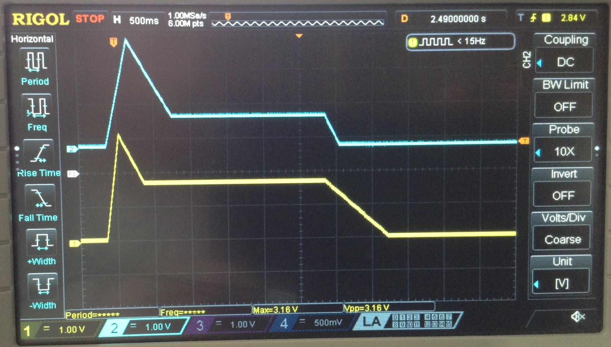
Here is a trace of both envelopes with different ADSR values running off the same trigger and gate:
Find it on GitHub here.
Closing Thoughts
To get any practical use out of this will require some electronics. I can’t just hook the DAC up to something else and expect everything to place nicely, so that is something to consider next.
But for now, although the code is more complex than I original thought, thanks to having to handle the interplay of triggers and gates, it seems to work pretty well.
Kevin
https://diyelectromusic.wordpress.com/2024/04/07/esp32-dac-envelope-generator/
#dac #envelopeGenerator #esp32 #mozzi