Fillet o’ Fish: Phillies 2, Marlins 1 https://www.rawchili.com/mlb/117324/ #Baseball #fillet #fish #FrontPage #good #Marlins #Miami #MiamiMarlins #MiamiMarlins #MLB #o #phight #Phillies #the
#Fillet
#ModernIonicCapital sketch
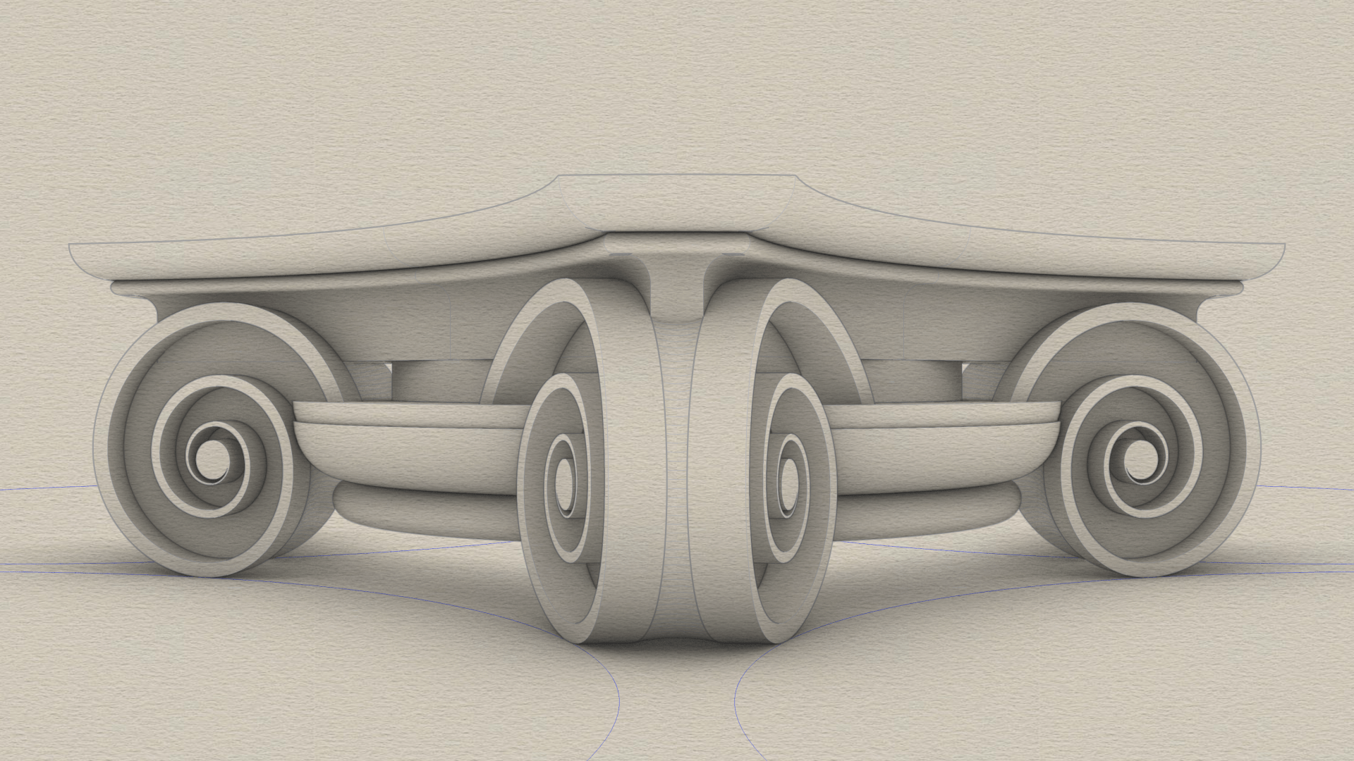
The modern #IonicCapital with curved faces and radial symmetry is a drop-in replacement for the classic Ionic capital with flat faces.
Unlike the classic variant, which has a rectangular footprint, the modern variant has a footprint that fits in a square. In the classic variant, the volutes and scrolls project out so that they are visible from the top. In the modern variant, there are no scrolls, the volutes have a curved face, and they are completely nestled under the top.
The sketch omits the #fillet at the bottom because we added that to the column #shaft in https://pixelfed.social/p/Splines/791794072490907090.
So, we start at the bottom with an #astragal which is exactly the same size as in the classic variant.
Next up from the bottom is the #ovolo which is shorter than in the classic variant. It still has a #tectonicSurface on which #decorativeElements rest, and a #virtualSurface that envelops the decorative elements. In this case, I chose a minimalist design with no #eggsAndDarts. Instead, I use another plain ovolo as a substitute that is offset from the tectonic surface by 1 part (or 8 units, when µ = 144).
Above the ovolo is the #channel, which in this case is a round slab whose surface matches the neck of the column with a radius equal to 5/6 of µ (120 units).
Above the channel is the #abacus which has a curved face that is repeated on all four sides. There is an abacus with flat sides in the classic variant as well, but it is not visible from the front because it is hidden behind the #volute slab. In fact, the vertical #braidsAssembly in the classic variant is attached to the abacus.
Above the abacus is a #reed, and above that, another small Ovolo that tops the modern capital.
The curved volutes follow the blue circular arcs at the bottom of the sketch. The volutes are shaped like a wedge, as can be seen more clearly in the corner facing the front. The portion of the wedge between the outer rims has a concave surface.
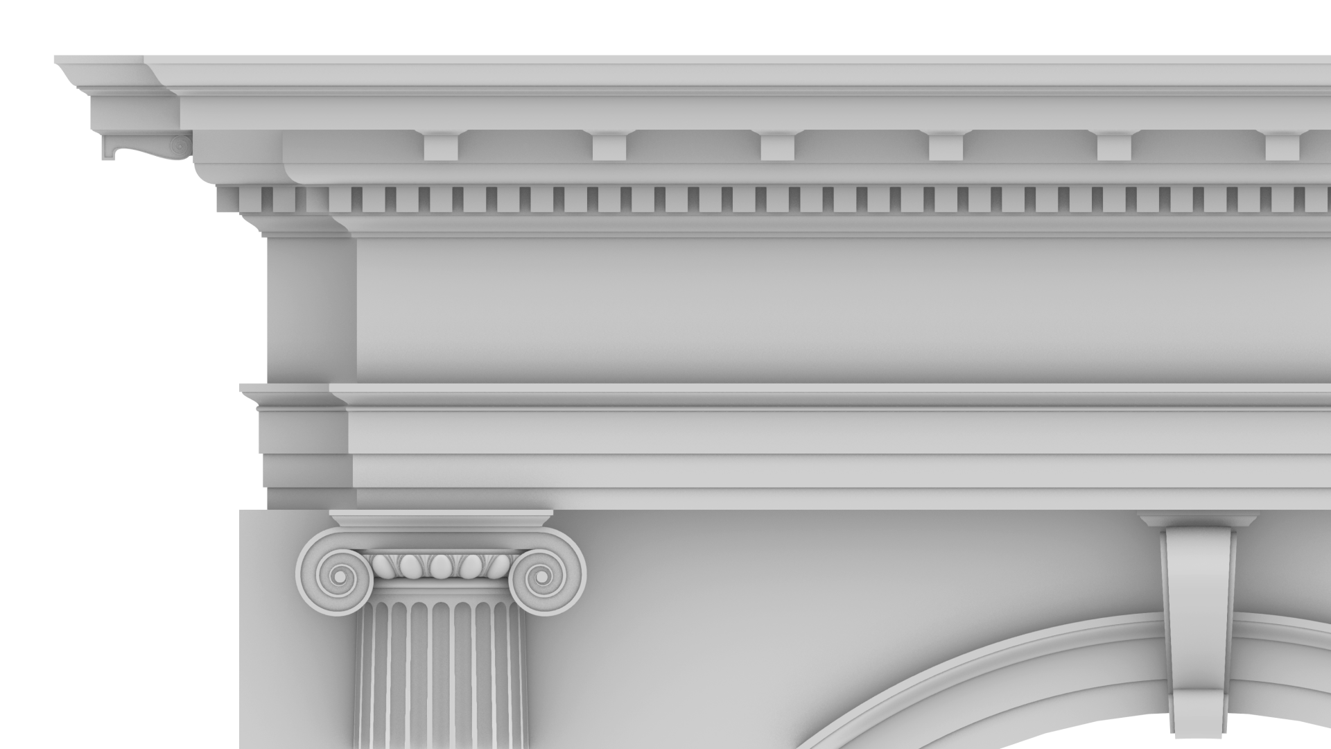
#ModernIonicEntablature with #modillions and #dentils adapted for #arcadeIntercolumnation.
This image shows modillions across the top of the entablature, including modillions visible on the side wall. The dentils are below the modillions and are a bit shorter than in the classic variant.
As with dentils, a #modillion must be centered on a column axis. In the front, there are two modillions directly above the two columns and eight other modillions equally spaced between them. The number is always 10. So the spacing is different for an #arch with no #pedestals.
This image also shows a skinnier #keystone. Its thickness is half that of the one shown in https://pixelfed.social/p/Splines/804548474524642209 but all other measurements remain the same. There is never a modillion directly above the keystone.
The #cymaReversa and #fillet above the keystone have #profileCurves identical to those in the #capital but the top is a square that is only µ x µ units. The top slab is centered front to back on the face of the arch.
In this image, the modern entablature is shown with the classic capital, but it goes really well with the #modernIonicCapital. As I mentioned in https://pixelfed.social/p/Splines/791065657488081419, the classic variant of the column capital has parallel flat #volute slabs only visible from the front and back, but not from the sides. Because of its lack of radial symmetry, the capital does not look as satisfying when viewed from the side, especially in a #colonnade, as seen in https://pixelfed.social/p/Splines/803089629244302486.
The modern variant has curved volute faces on all four sides with pointed ends at all corners and optimized for use in a corner column, but not limited to that. The modern #IonicCapital is the last remaining piece in our systematic look at the complete #IonicOrder.
This concludes our look at the entablature, both classic and modern, and both for #simpleIntercolumniation, or #Architravato, and #arcadeIntercolumniation.
#Arcade #Intercolumniation without #Pedestal
In https://pixelfed.social/p/Splines/803089629244302486, we saw #simpleIntercolumniation, also known as #Architravato.
Roman architects combined columns with walls thick enough to bury half of the column width inside the walls and added arches to them for better load distribution. An arcade (multiple arches) can be run in series along a single wall, or in parallel to form a walkway. They can also be combined in both series and parallel configurations, perhaps the most famous of which is the #Colosseum in Rome.
In the Colosseum, the outer walls follow an elliptical curve (even though it looks circular from the outside), and it has multiple tiers of arches in series. The interior has arches in concentric passageways in the lower tiers giving it a lattice-like design.
Because arches distribute the load from above, they allow for wider intercolumniation. The rules for #ArcadeIntercolumniation differ depending on whether the columns have pedestals or not.
Besides the arch itself, which is part of the wall, the figure shows some new architectural elements.
The narrow part of the wall immediately behind a column is known as a #pier. The visible face of a pier between a column and the opening under the arch is known as #alette. The base of the pier has a molding, the flat part of which has the same height as the column base (µ) while the rest follows the #fillet and #cavetto or #conge of the #shaft.
As we move up the pier, there is a horizontal molding known as #impost just below where the arc of the arch starts. The impost wraps around on the sides of the pier.
Around the arc is a circular molding known as #archivolt, the bottom portion of which has a #fascia that is aligned with the face of the wall.
The wall itself extends all the way to the top of the #entablature. It is worth noting that the entablature is repeated on the wall. It doesn't end at the columns and has two "outside" corners and one "inside" corner.

#IonicColumn #Flutes
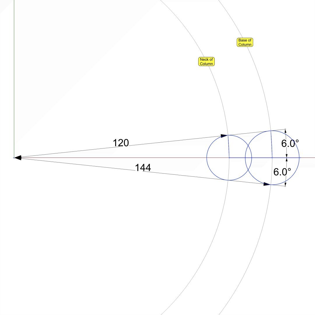
This diagram shows the 2D geometry of an #Ionic #flute. The larger blue circle shows the flute outline near the #base of the #column. The smaller blue circle shows the flute outline near the #neck of the #shaft. Both subtend a 12° angle at the center of the column.
Like an egg in the #EggsAndDarts motif, a flute must be centered on the column axis when viewed directly from the front, back, or the sides. This is why the 12° are split into 6° on either side of the X axis. The center of the larger circle is µ = 144 units from the origin on the X axis. The center of the smaller circle is 5/6 of µ, or 120 units from the origin.
In https://pixelfed.social/p/Splines/799340150182400358, I mentioned working at sub-micron precision, and you might wonder where that came from when we have been using abstract units like µ without specifying any physical units. My apologies for not making it clear that I had assumed 1 unit was equal to 1 mm. If that assumption holds, then µ = 144 mm gives a total order height of 4104 mm, that is 13.46 ft. At smaller scales, the precision is even higher than 1/10 of a micron.
With that said, here the radius of the larger circle is 15.0728 units and that of the smaller circle is 12.5606 units, with sub-micron precision if 1 unit = 1 mm.
Refer to https://pixelfed.social/p/Splines/791399680747885646 and place the center of the smaller circle exactly at point J on the neck line. Later we will draw a sphere at the same location with the same radius.
If you want a flat bottom for flutes, place the center of the larger circle at exactly 28 units (12 for the #fillet and 16 for the #cavetto or #conge) above point A in that figure. If you want a round bottom, then further move the larger circle up by the size of its radius.
Nobody would quibble if you used a radius of 15 units instead of 15.0728 units, but it would make it easier to switch from flat to round bottom or vice-versa by simply moving the circle up or down 15 units.
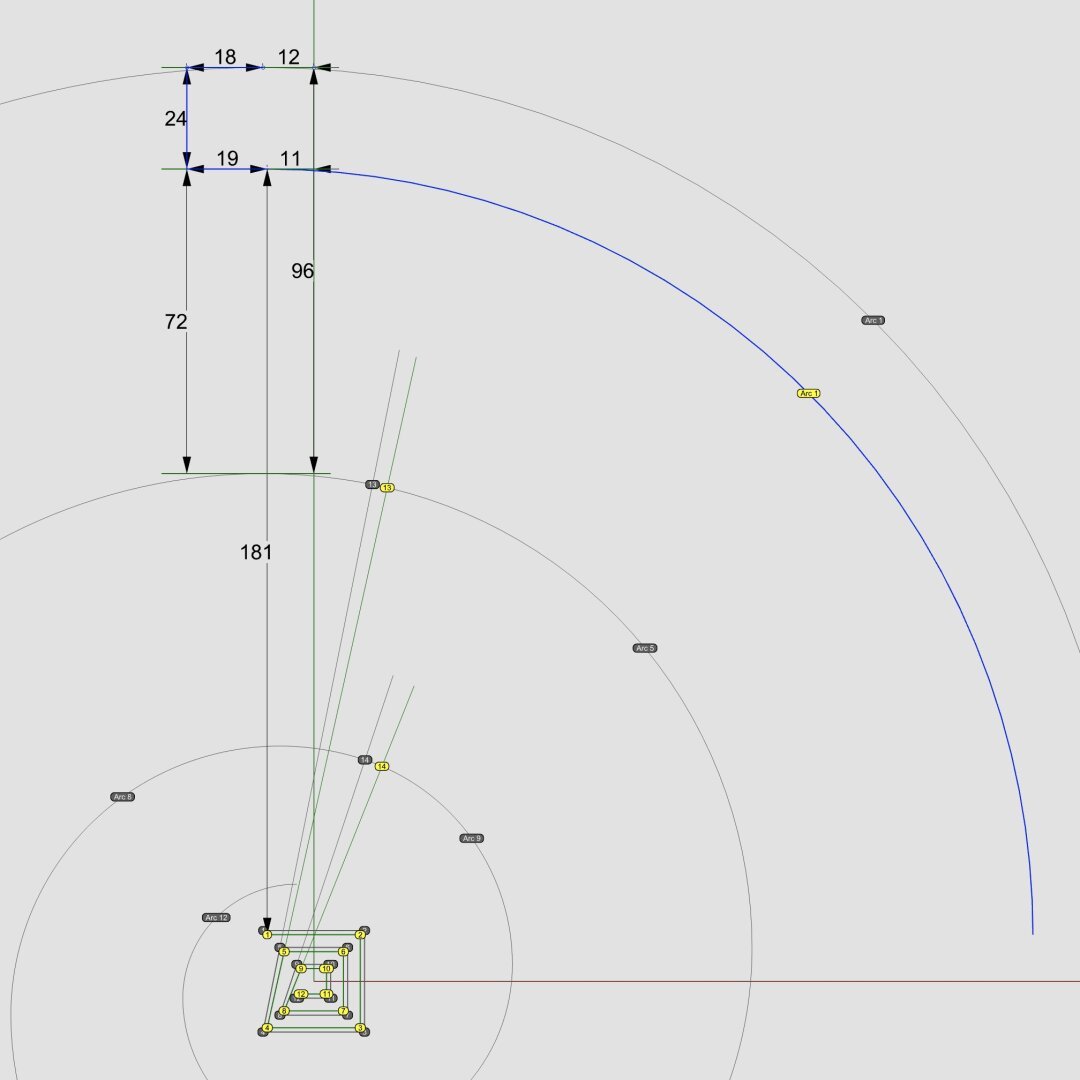
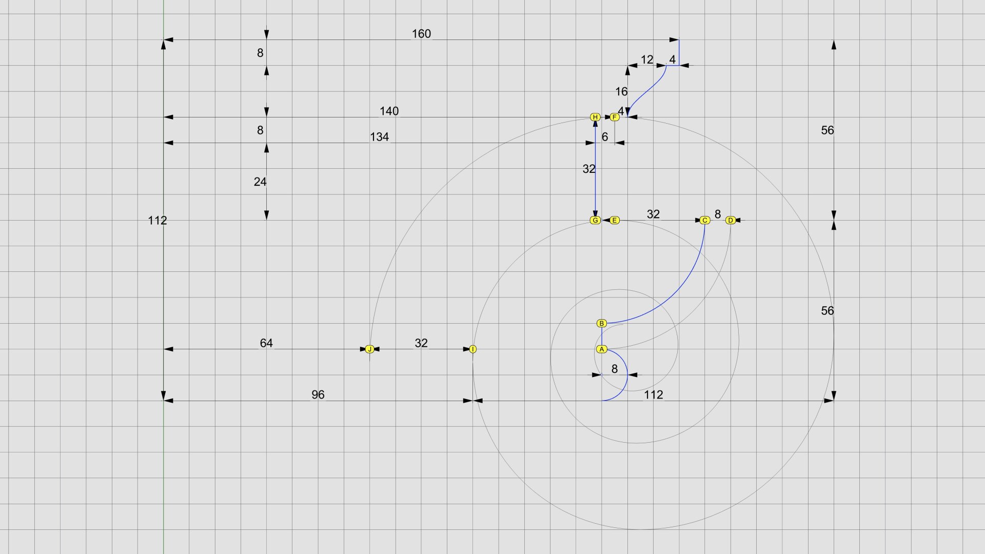
In https://pixelfed.social/p/Splines/792511464365923534 we created the outer spiral for the #IonicVolute. We will now create the inner spiral. Remember that we're temporarily using a 3x scale.
Recall from https://pixelfed.social/p/Splines/792124787573855518 that the vertical gap between the maxima for the 2nd turn of the spiral and that of the first turn shown by points G and H, respectively, is exactly 4 parts or 32 units when µ = 144. With a 3x scale, it is still 4 parts, but each part is 24 units, so gap is 96 units now. Of these 4 parts, 1 part (now 24 units) is the #fillet that gets progressively narrower as it follows the spiral, and 3 parts (now 72 units) form the #channelGroove.
The volute extends 3/4 parts or 18 units now (6 units in the original) to the left of the point of horizontal tangency of the outer spiral. This is the amount needed to accommodate the ribbon and 3-strand #braid on the flat vertical wall on the sides of the #capital as shown earlier in the same post by points F and H.
Now focus on the square where we have the 12 numbered vertices. At present scale, the square is 1 part or 24 units wide. Now inset each concentric square by 1 unit on each side, effectively dividing the gap between the original squares in a 1:3 ratio — same as the fillet height to groove size ratio.
Move to new point 1 in the square and sweep arc 1 of the inner spiral using a radius of 181 units so that the vertical gap between the top of original arc 1 and new arc one is exactly 1 part (24 units at present scale), and the vertical gap between the start of new arc 1 and the old arc 5 is exactly 3 parts or 72 units.
Continue with inner arc 2 from where inner arc 1 ended, using new point 2 as the center. Finish drawing the entire inner spiral exactly as described earlier for the outer spiral. This time you don't need arc zero or the outer circle unless you are contemplating a #medallion.
All that's left now is to complete the #eye of the volute, which I show next.
Classic #IonicCapital #Tectonic Surfaces Plan
We already made the 8 unit tall #fillet at the bottom of the #capital a part of the #shaft in https://pixelfed.social/p/Splines/791794072490907090. So, excluding that, the remainder of the capital is 14 parts or 112 units tall, for the bottom half of which we use the #revolve operation (like the #columnBase and #columnShaft), and for the top half we use the #extrude operation (like the #pedestal, #entablature, and #plinth).
Starting at the bottom, we have an #astragal that is 2 parts or 16 units tall and has the same profile as a #reed and #torus, falling in between the two in terms of size. The arc AD is shown in gray because it is an invisible #virtualSurface that envelops the decorations like #eggsAndDarts on the #ovolo. This is the measurement that is given in #Scarlata's #PracticalArchitecture, but it makes no mention of the #decorative and #tectonic surfaces. Arc BC with a radius of 4 parts or 32 units is the tectonic surface on which the Ovolo decorations rest. Such decorations have a variable or uneven surface which may not exceed 1 part or 8 units.
Points E and F mark the horizontal tangent or maxima of the second spiral and the first (outermost) spiral, respectively. The gap between them is exactly 4 parts or 32 units. GH is the profile for the vertical side surface on which part of the #ribbon and #braid lie flat, protruding exactly 6 units to coincide with the invisible virtual flat surface through EF.
The #cymaReversa is 2 parts or 16 units tall and 1.5 parts or 12 units wide. It starts 4 units to the right of F and stops 4 units short of the top fillet, which is one part or 8 units tall and 20 parts or 160 units from the #columnAxis.
Of the 4 parts or 32 units between G and H, the lower 3 parts or 24 units are part of the #voluteChannel groove and the top 1 part or 8 units is a fillet that follows the curve of the #volute and progressively gets narrower until it converges with the #eye of the volute.
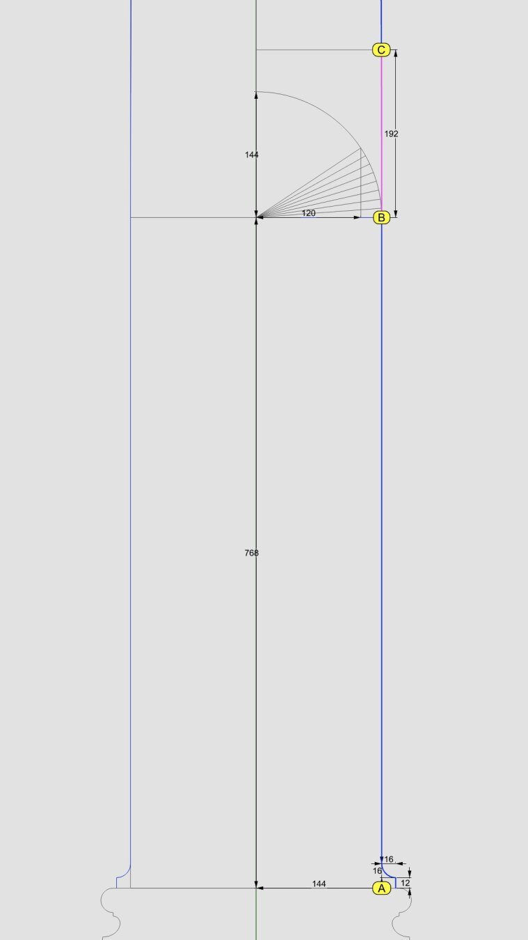
The bottom 1/3 of the #columnShaft for an #IonicColumn is a perfect cylinder. So the line below point B is a straight line.
In https://pixelfed.social/p/Splines/791723063470910081, we blended the bottom end of the 60° arc and the top end of the long interpolated curve between points J and K. Now blend the bottom end of the interpolated curve and the top end of the straight line between points B and C to obtain the 3rd and final #NURBS segment for the #primaryProfileCurve of the shaft.
Just like there's a #cavetto and #fillet near the #neck of the shaft, there is a fillet and cavetto near the foot of the shaft. However, there is a subtle difference between the two. The cavetto near the neck is tangential to the blended #NURBS curve that is not a straight line. The profile curve for the cavetto near the foot is tangential to a straight line.
There is a special name for a cavetto that is tangential to a straight line or flat surface, like the two cavetto moldings in the #dado of the #pedestal. It's called a #conge. Another alternate name for the cavetto molding is #cove, which is evocative of "cave" because of its concave profile curve.
Above the neck is a fillet 8 units tall and an #astragal 16 units tall that #Scarlata puts in braces in the column shaft section within his tables of #VignolaProportions, with a note saying they are not counted as part of the shaft but are accounted for as part of the #capital.
I decided to include the top fillet as part of the shaft and keep the astragal with the capital. It does not change the design or alter the proportions in any way, but the inclusion of the fillet makes it more practical for #3DPrinting and #CNCMilling of the neck. This concludes the profile curve for the shaft with a height of 291 parts or 2328 units + 8 for fillet.
The column shaft is tapered in the upper 2/3 due to #entasis whose purpose is to make optical corrections to the shape of the column which, without correction, appeared concave near the top.
#IonicColumn #VignolaBase and #AtticBase #CAD Plans
Both #Vignola base and #Attic base have the same square footprint of 400 units x 400 units. The #plinth for both is 48 units (6 parts, or µ/3) tall, and the total height for both is 144 units (18 parts, or exactly µ). As such, they are easily interchangeable.
In the Vignola variant, we start at the plinth with a #fillet 2 units tall and a classic #scotia 18 units tall gouging out part of the fillet.
Then there is another fillet 2 units tall, followed by two #reeds, each 8 units tall, followed by another classic scotia as described above.
This is followed by yet another fillet 2 units tall and topped off with a #torus 40 units tall. A Torus is the same as a reed, except larger. When we reach the neck of the shaft, we will see another molding called #Astragal which has the same profile as reed and torus, but sits in the middle in size. Think of reed, astragal, and torus as small, medium, and large of the same profile.
The modern Attic variant is more elegant with fewer moldings. It also gives the impression of more heft for more stately columns. It starts at the plinth with a torus 36 units tall, followed by a fillet 4 units tall, followed by a modern scotia 24 units tall, followed by another fillet 4 units tall, and topped off with another torus 28 units tall.
As in the construction of #IonicEntablature [https://pixelfed.social/p/Splines/791013152244518907], split the construction of the #columnBase into two steps.
Just as we extruded #dentils separately, we extrude the plinth separately. First draw a square 400x400 in the top view. Then extrude the square 48 units in the front view.
For the rest of the base, we need a new 3D operation — #revolve around an axis. Instead of extruding the #primaryProfileCurve, we revolve it around the #columnAxis, and cap the #planarHoles on both ends before performing a #booleanUnion with the plinth. Finally check edges of the solid for #nakedEdges and #nonManifoldEdges.
If you've been longing for some 3D adventure, your wait is over. We have here some of the most basic 3D operations that you will use over and over.
First #join all #primaryProfileCurves into a single curve that has both straight lines and arcs. If you are unable to join them, look closely at the bottom #fillet of the #dado where it meets the top of the #reed of the #basement. There is a gap of 2 units between the fillet and the arc of the reed. Close the gap with a straight line and join the curves.
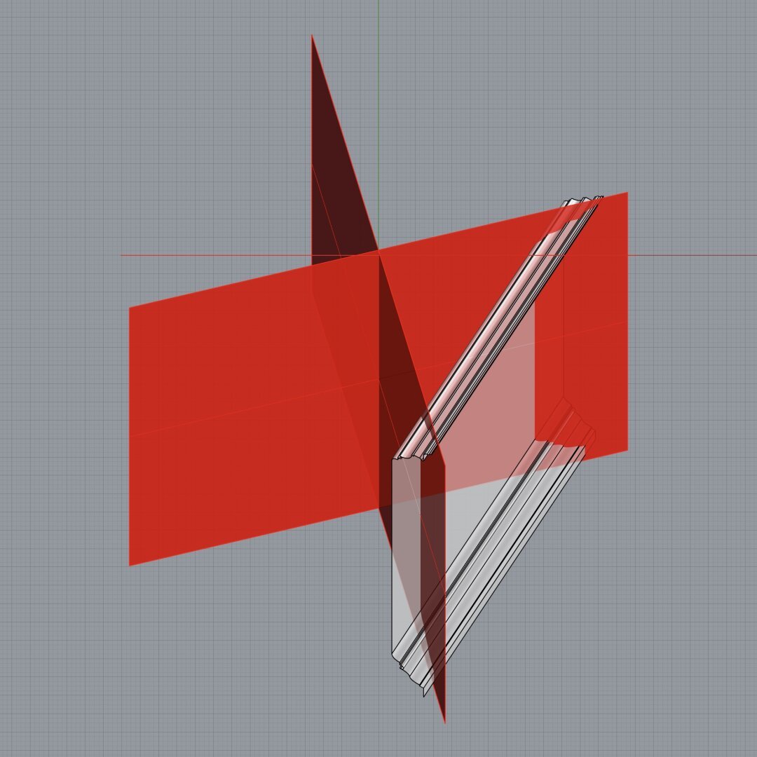
Switch from the front view to the right view, and #extrude the joined profile curves on both sides of the profile curve so that the full extrusion is a little over the total width of the pedestal. A good rule of thumb is to extrude at least 1/8th extra on both sides of the joined profile curve. This extrusion is shown in the attached image as the gray surface in perspective view.
Switch back to the front view and centered on the #columnAxis, draw a rectangle that is somewhat taller than the total pedestal height so that it extends past both the top and bottom of the pedestal extrusion from the previous step. The total width of this rectangle should be about 1.5 times the width of the pedestal. This is because we will create a cutting surface with this rectangle and rotate it 45° in the top view, and then rotate a copy of that another 90°, as shown by the flat red surfaces. The reason the width must be approximately 1.5 times (or larger) is because #Pythagoras told us that the hypotenuse of a unit square is 1.414 units. So 1.5 times should be enough.
Use the two cutting planes to cut, split, or trim the extruded surface (depending on the terminology of your CAD program). This is called #mitering. Discard the excess of the extruded surface from both ends. Also discard or hide the red mitering surfaces.
Switch to the top view and rotate the #mitered extrusion repeatedly at 90° about the column axis until you have all four sides, and join them all into an open surface.
First #join all #primaryProfileCurves into a single curve that has both straight lines and arcs. If you are unable to join them, look closely at the bottom #fillet of the #dado where it meets the top of the #reed of the #basement. There is a gap of 2 units between the fillet and the arc of the reed. Close the gap with a straight line and join the curves.
Switch from the front view to the right view, and #extrude the joined profile curves on both sides of the profile curve so that the full extrusion is a little over the total width of the pedestal. A good rule of thumb is to extrude at least 1/8th extra on both sides of the joined profile curve. This extrusion is shown in the attached image as the gray surface in perspective view.
Switch back to the front view and centered on the #columnAxis, draw a rectangle that is somewhat taller than the total pedestal height so that it extends past both the top and bottom of the pedestal extrusion from the previous step. The total width of this rectangle should be about 1.5 times the width of the pedestal. This is because we will create a cutting surface with this rectangle and rotate it 45° in the top view, and then rotate a copy of that another 90°, as shown by the flat red surfaces. The reason the width must be approximately 1.5 times (or larger) is because #Pythagoras told us that the hypotenuse of a unit square is 1.414 units. So 1.5 times should be enough.
Use the two cutting planes to cut, split, or trim the extruded surface (depending on the terminology of your CAD program). This is called #mitering. Discard the excess of the extruded surface from both ends. Also discard or hide the red mitering surfaces.
Switch to the top view and rotate the #mitered extrusion repeatedly at 90° about the column axis until you have all four sides, and join them all into an open surface.
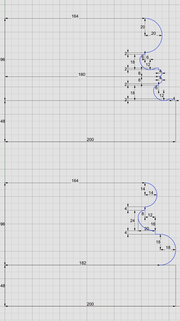
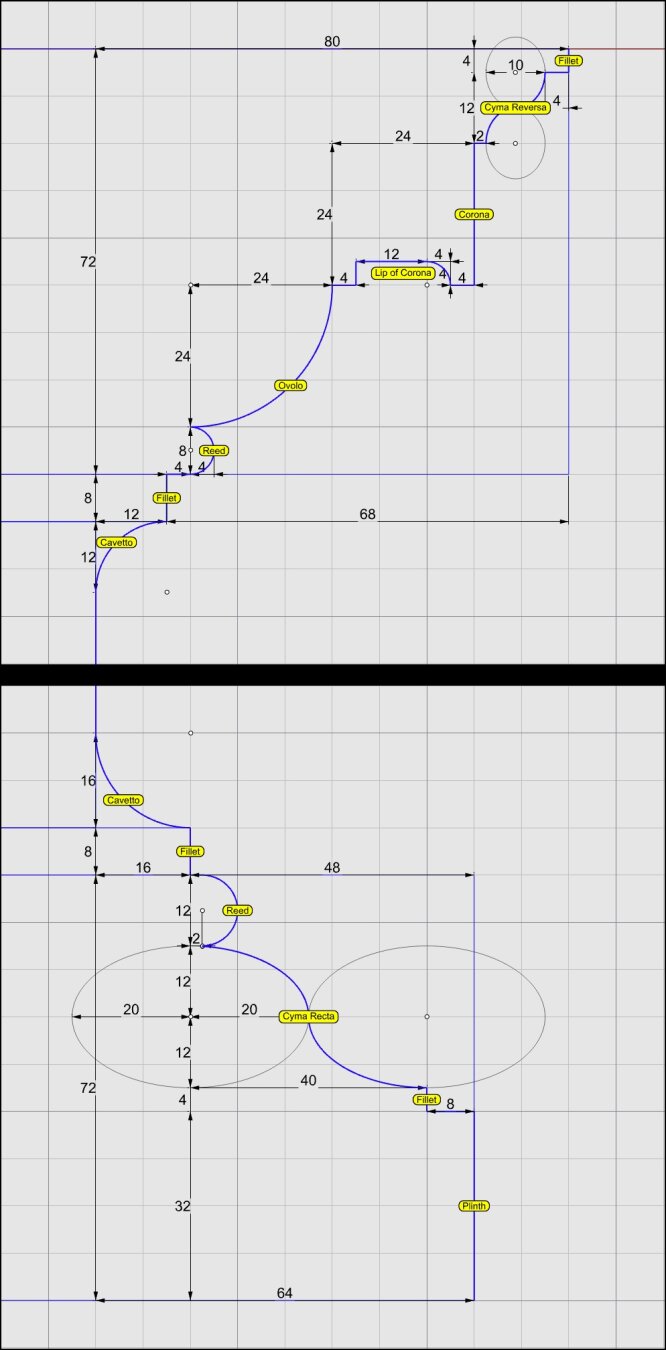
This shows the detailed measurements of the top and bottom portions of the #IonicPedestal. For macro-level measurements, see https://pixelfed.social/p/Splines/790571135473463588
Each of the blue curve segments (lines and arcs) that are marked with a yellow bubble is the #profileCurve for a #molding whose name is inside the bubble.
Starting at the bottom, we have a #plinth, a #fillet, a #cymaRecta, and a #reed as part of the #basement of an Ionic pedestal.
Next up, we have a #fillet and a #cavetto at the bottom of the #dado, and another cavetto and fillet at the top of the dado.
Moving higher up, a reed, an #ovolo, a #corona, a #cymaReversa, and a final fillet top off the cap of the pedestal.
They are called profile curves because each is the outline or silhouette of a 3D molding as seen from one side or in a cross section. In the case of a pedestal, these curves can be used directly to recreate the 3D shape of the pedestal. For this reason and in this case, I call them #primaryProfileCurves.
This is not always the case. For more complex shapes, such as the #scroll surface of an #IonicCapital shown in https://pixelfed.social/p/Splines/789956327130679640, the profile curves recovered by #reverseEngineering the image scans in #Vignola's book cannot be used directly to sweep the scroll surface because the scroll shape is not cylindrical. Like the inside of a rose, the scroll surface follows the outlines of spiral #volutes in the front and back, neither of which are circular. So, additional steps are necessary to derive the curves that we can actually use to reconstruct the surface.
In the case of the scroll surface, the derivation of these curves is not trivial and not obvious, but it is not difficult to understand, and no math is involved. There are multiple sets of curves, and each successive set is derived from a previous set. I call them secondary, tertiary, and quaternary curves.
For now, we stick with the primary profile curves for the pedestal.
⬆️ #IonicPedestal #3DModeling #SurfaceExtrusion
Ensure that all #ProfileCurves segments are joined into one curve and extrude it along the right side of the pedestal to a little over the maximum distance the curve projects from the column axis.
In this case, the maximum projection is 280 units for the top #fillet of the #pedestal #cap. So, extending it to 300 on both sides for a total length of 600 units should be sufficient.
This shows a perspective view of the outside surface before mitering
⬆️ #IonicPedestal #3DModeling #ProfileCurves
Top-right portion of profile curves for #Ionic Pedestal. Details in Alt text.
When µ = 288, the pedestal #Cap is 72 units tall. The #fillet and #cavetto below that are part of the #Dado.
The #Ovolo is convex (opposite of cavetto). Both Ovolo and #Corona are 24 units tall.
The corona has a lip that is not visible from front. The function of the lip is not to help you lift the pedestal and move it around but to dissipate water dripping from the top.
⬆️ #IonicPedestal #3DModeling #ProfileCurves
Bottom-right portion of profile curves for Ionic Pedestal. Details in Alt text.
Starting from bottom, the #plinth, #fillet, #CymaRecta, and #reed belong to the #Basement.
The fillet and #cavetto (circular arc) above those belong to the #Dado.
The cyma recta is 40 units wide and 24 tall. So the arcs for that are cut from ellipses.
A refined variation of cyma recta uses half turn of a helix instead of 2 elliptical arcs and will be presented later.
💡 What is a Fillet Rectangle in AutoCAD?
AutoCAD is a powerful software for designers and engineers. A fillet rectangle is a geometric shape with rounded corners. This guide will show you how to easily create a fillet rectangle using AutoCAD. ✏️ #AutoCAD #Fillet
👇👇
https://youtube.com/shorts/evFY8FFulIQ?si=gxikknZhUvJXNnHG
@maarten Het is ondertussen weer zondag, dus het leed is geleden. Maar toch, een tip. Sinds een aantal afleveringen maakt het huis #Fillet-#Speybrouck de #podcast van de #UniversiteitVanVlaanderen: https://www.vrt.be/vrtnu/a-z/universiteit-van-vlaanderen/
Vertel het voort, want veel voormalige luisteraars van #InterneKeuken weten dit nog niet.
Client Info
Server: https://mastodon.social
Version: 2025.04
Repository: https://github.com/cyevgeniy/lmst