Forbidden Planet “Krell” Display
If you’re not familiar with The Forbidden Planet, then it is an iconic 1956 Sci-Fi movie with an absolutely ground-breaking soundtrack of “Electronic Tonalities” by Bebe and Louis Barron.
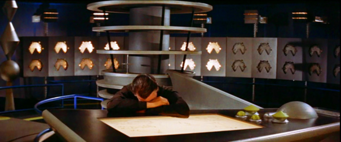
In one scene, when the humans visit an alien (the “Krell”) science lab there is a large set of display dials around the room that logarithmically show the power being generated by the Krell machine and I’ve been thinking for a while I’d like to try to reproduce them in a way that I could then use for something musical.
This post details the 3D and electronic design for my version of the Krell’s power indicators. The musical bit will hopefully follow at some point.
https://makertube.net/w/wmXGgm9GUeztDXn1K3nhmG
Warning! I strongly recommend using old or second hand equipment for your experiments. I am not responsible for any damage to expensive instruments!
If you are new to Arduino or 3D printing, see the Getting Started pages.
Parts list
- 3D printed Krell display unit
- Arduino Nano or Uno
- Several 7-way “neopixel”-like WS2812 5050 rings of LEDs (one per display face)
- Breadboard and jumper wires
Design and 3D Printed Case
I’ve opted to build the display in units of two or four. The original Krell setup has gauges one above the other as can be seen in this capture from the film.
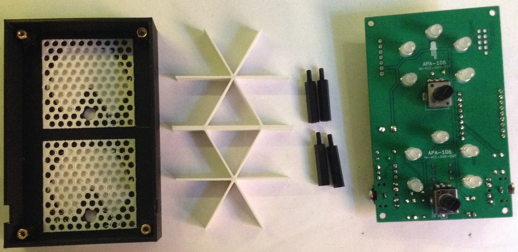
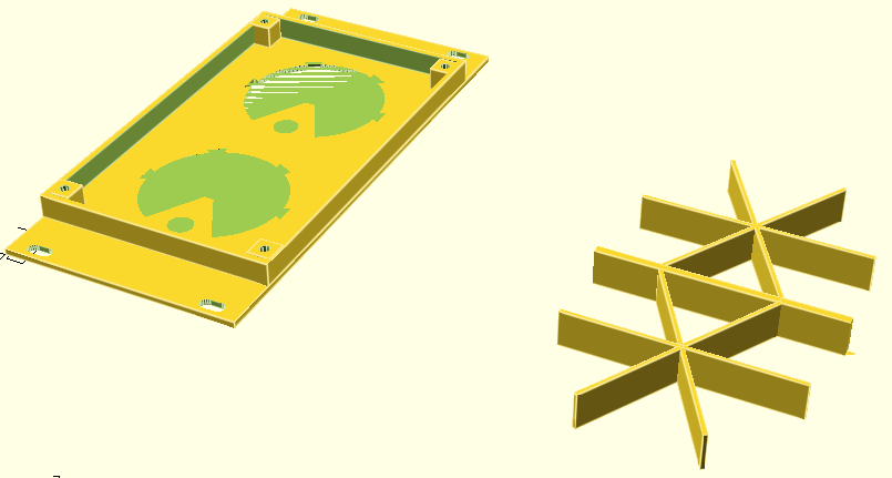
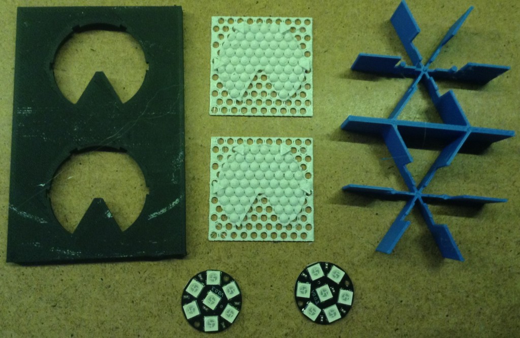
I’ve designed the display in four parts as shown below (these are early versions, but you get the idea).
The required “neopixel”-like rings are also shown. I actually only need 5 LEDs per display, but I need them to map onto the 5 cut-out segments on the display. This means that the bottom and centre LEDs are not used, but the other 5 map on quite nicely to the other of the six segments in the display.
OpenSCAD Code
I’ve used OpenSCAD and the code for all parts is in a single file. This means that any definitions relating to dimensions and scale can be used by all parts. Which part gets rendered and shown is selected at the top of the code.
show_frame = 1;
show_insert = 0;
show_support = 1;
show_quadframe = 0;
show_quadsupport = 0;
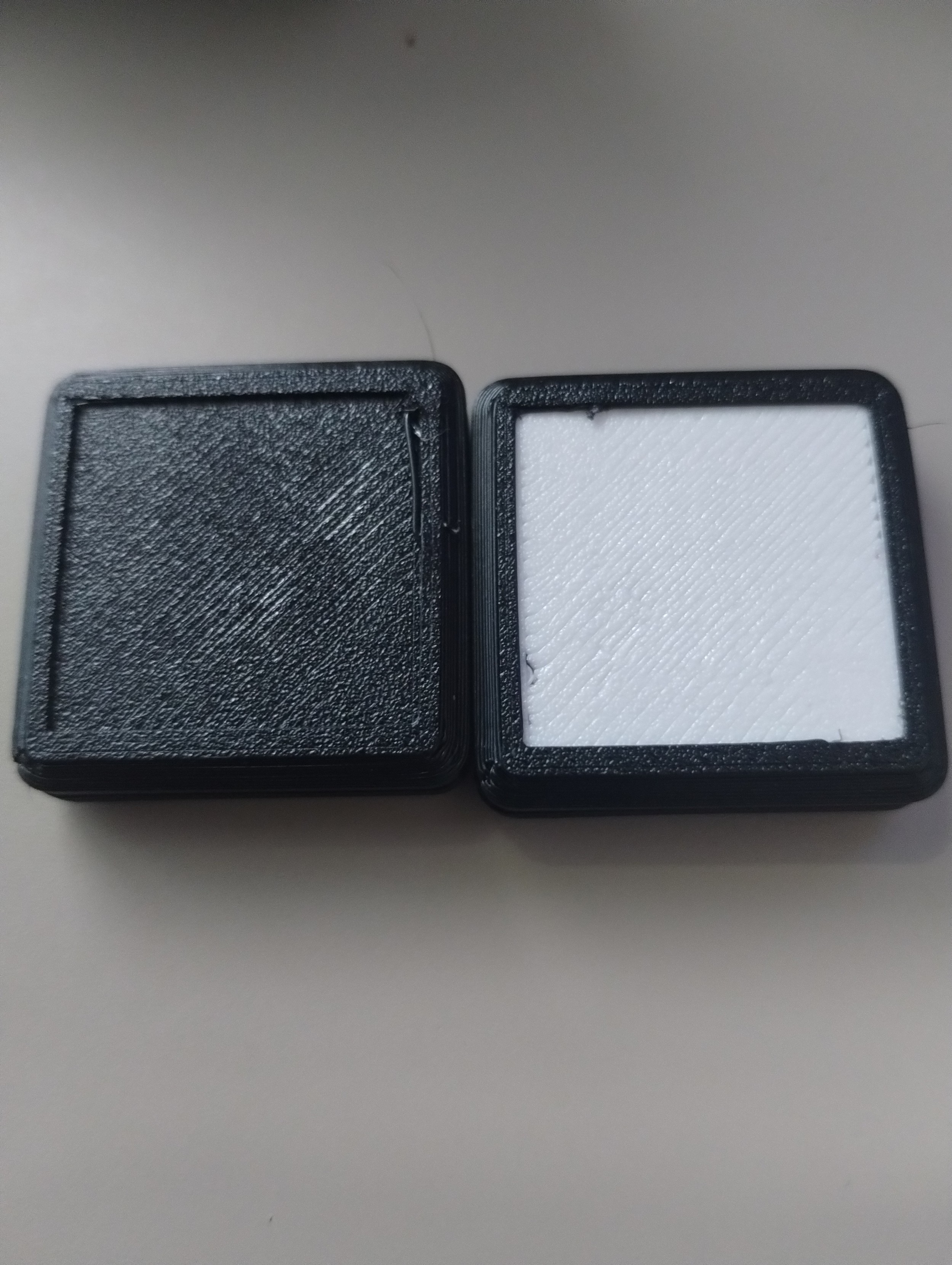
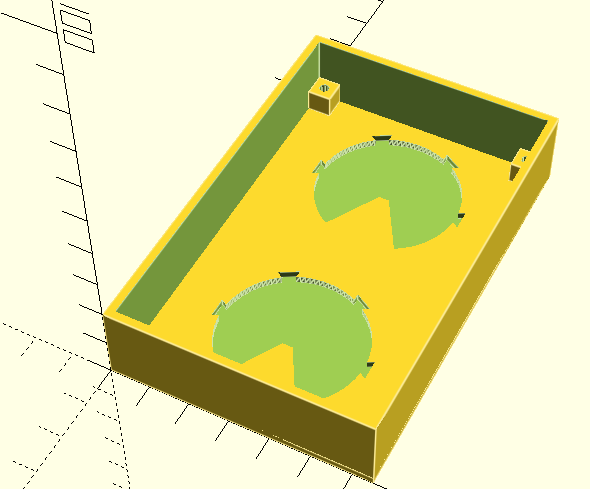
The inserts are the (white) display faces, and two of these are required per twin display. They also need a frame and optionally a support (if using the LED rings).
There is also a “quad” version of the frame and support which allows for a four-way display, which naturally will then require four inserts printing.
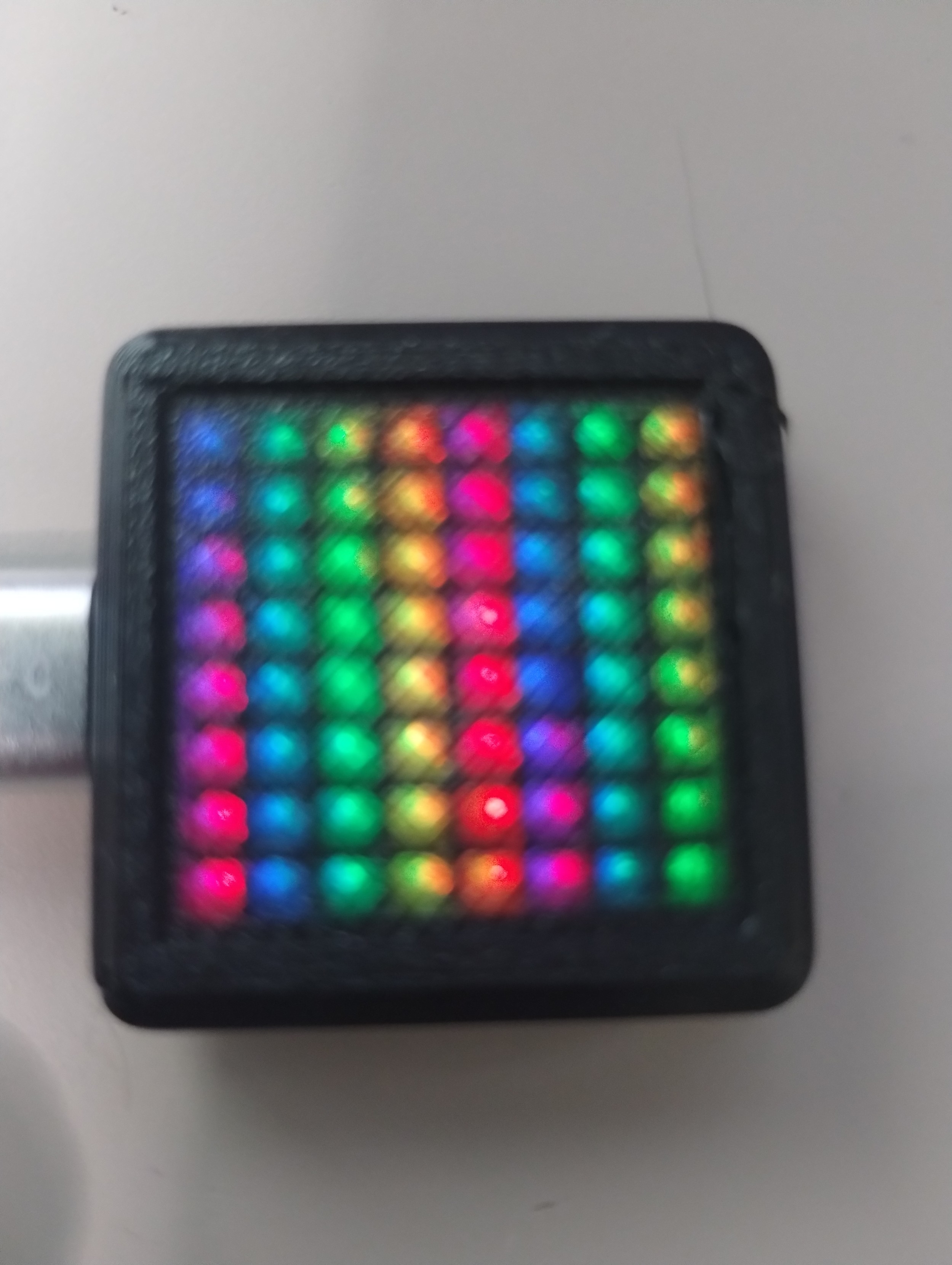
I’ve just used standard white PLA for the inserts and that seems to diffuse the LEDs nicely once lit. The frame and supports I’ve just used black and blue PLA respectively because that was what I had to hand at the time.
Here are the key parts in OpenSCAD for the dual-display.
And these are the parts for the quad display:
The actual insert for each display panel is a pretty complex object and takes a while to render on the display when moving and zooming. And even longer to render as an STL. There is probably a better way to design this, but it works ok for me.
In terms of the OpenSCAD code, there are the following modules:
- supports() – used to build the supporting partitioning for a single face of the display. This is called twice for a twin display and four times for a quad display.
- krell() – builds the display face itself for a single display, but is also used for the cutout for the face in the main frame. Again used twice in the twin display and four times for the quad.
- krell_mark() – used to create each of the four triangles that are part of each single display face.
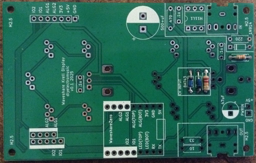
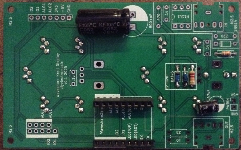
- pcbfixing() – used to create a pillar with a M2 sized hole that could be used to mount a PCB.
- sector() and arc() – used to build the six individual segments. It is taken from https://openhome.cc/eGossip/OpenSCAD/SectorArc.html
It’s perhaps not the most efficient, and certainly is the cause of the longer rendering times for the insert, but I’ve made quite heavy use of difference() and union() to create the various cut-outs and masked-off areas.
The face panel was particularly challenging, using combinations of spheres and cylinders. I particularly wanted the spheres to be hollow so they didn’t show up darker when illuminated from behind. Packing the spheres in also involved calculating the vertical distance using the formula: vertical position = radius * SQRT (3) and then offsetting the start of the next row by a single radius.
Design notes:
- I planned to allow for a PCB to be made and mounted in the case. This would make for a nice, self-contained unit, hence the PCB fixing points. But in the end opted for the “neopixel” style rings and jumper wires.
- The supporting partitions originally included mounting points for the M2 holes in the rings, but they proved either too small and brittle or too large. I don’t know if that was an issue that could be solved by tweaking the resolution of the print, but in the end the rings wedge in fairly well without them.
- There is little provision for wiring at the moment or for mounting a microcontroller. The units themselves are cases and LEDs rings only.
- I’ve not found any dimensions online for the displays, but from photos of props that have been sold online, I decided on the ratio 65:100 for the displays, so used that in mm for my twin display. They “feel about right” to me.
Find the source and STL files on GitHub here.
Arduino Electronic Control
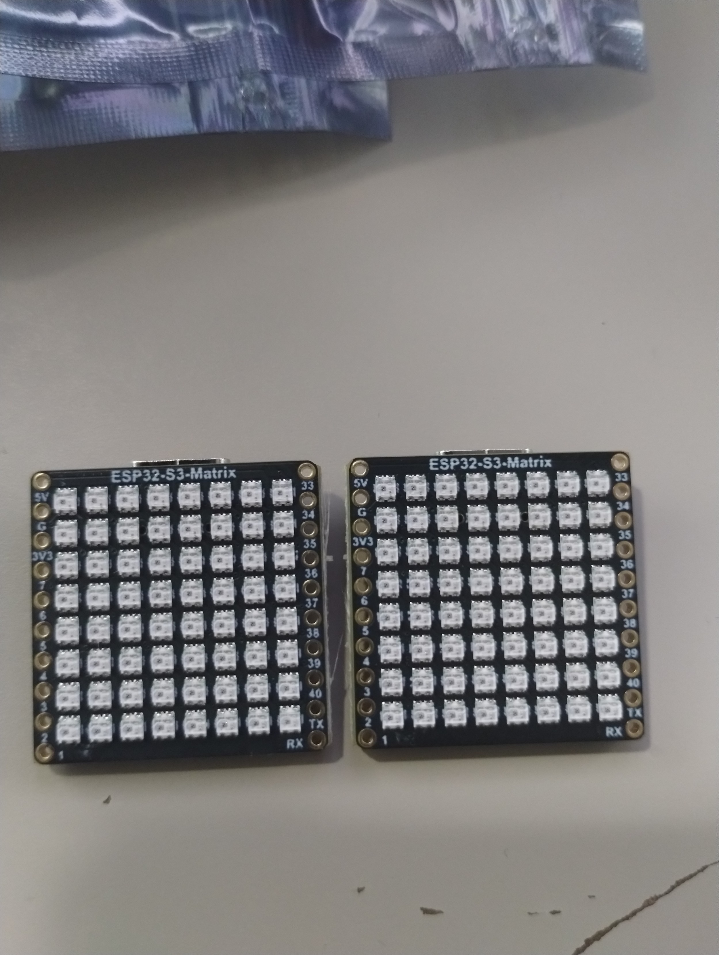
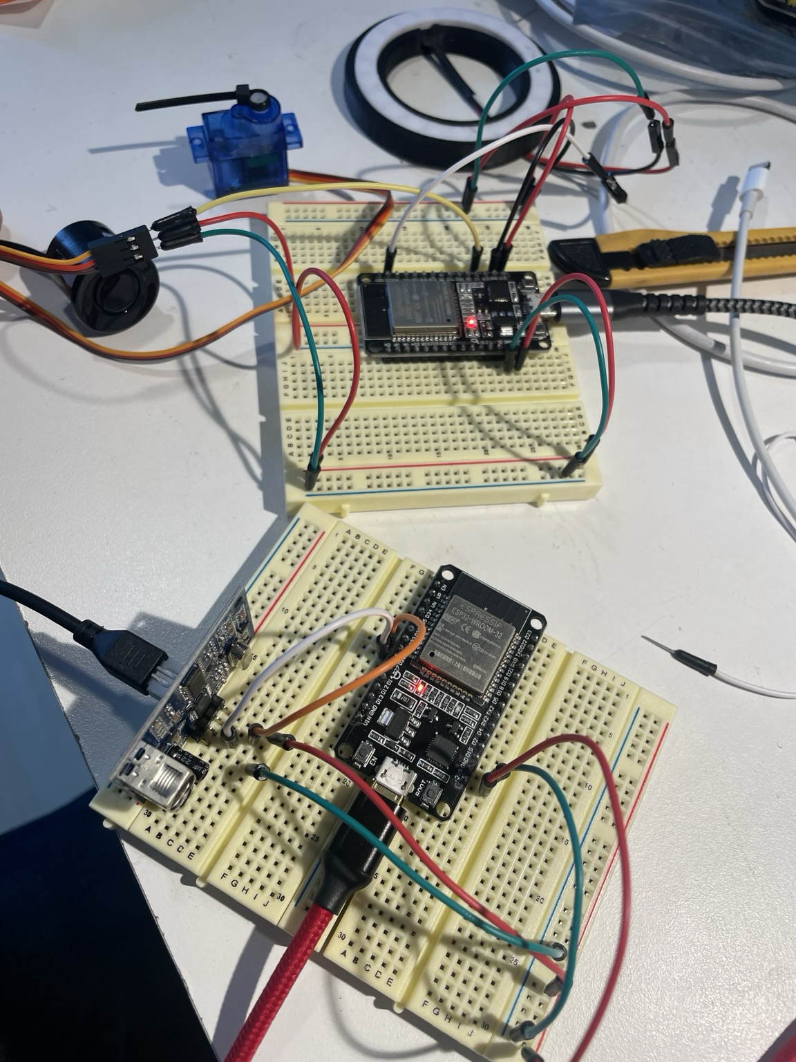
I’m using an Arduino Nano but pretty much any 5V microcontroller would do. If using a 3V3 microcontroller, then level shifting would probably be required as these LED rings really do nee 5V for power and signals.
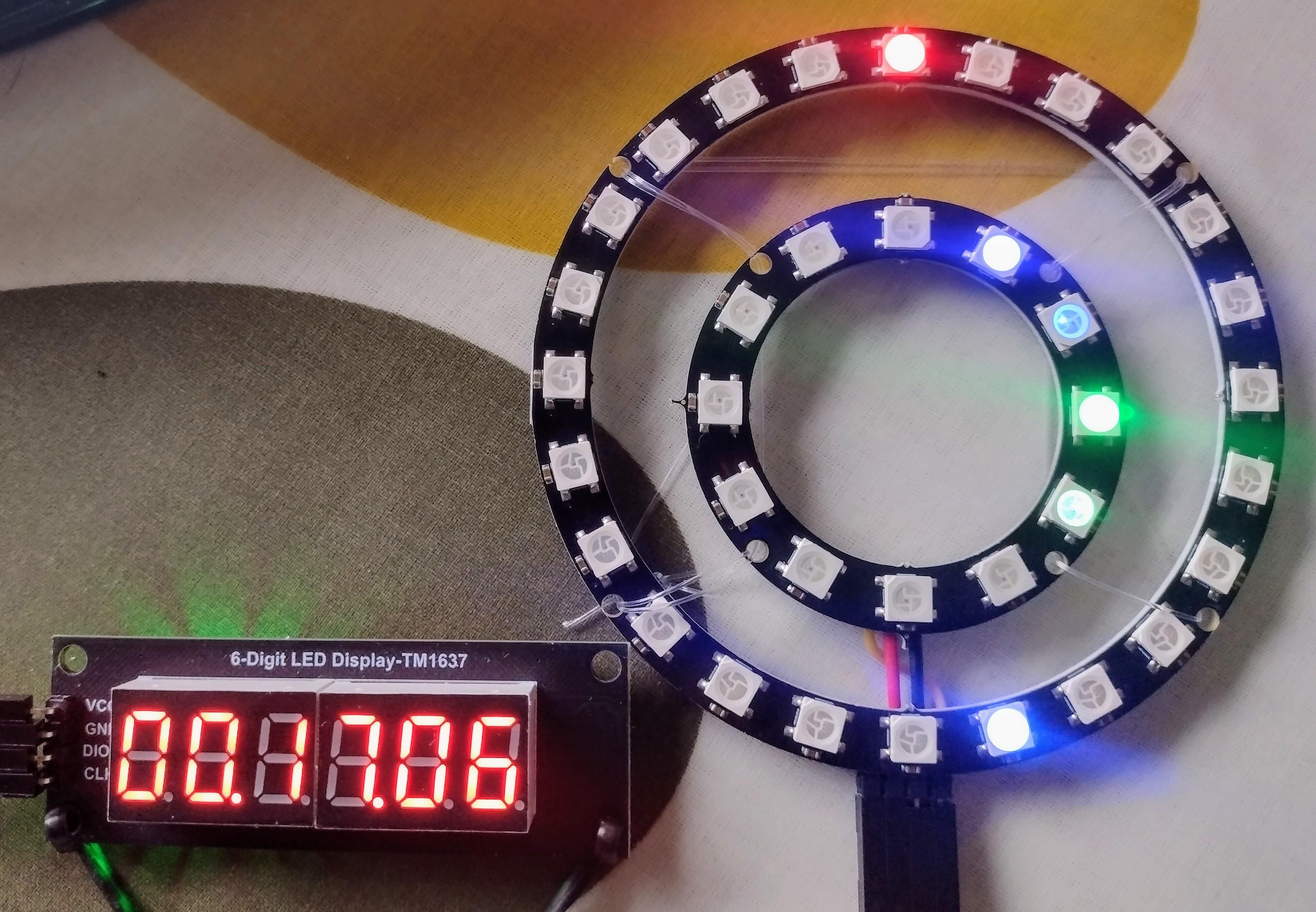
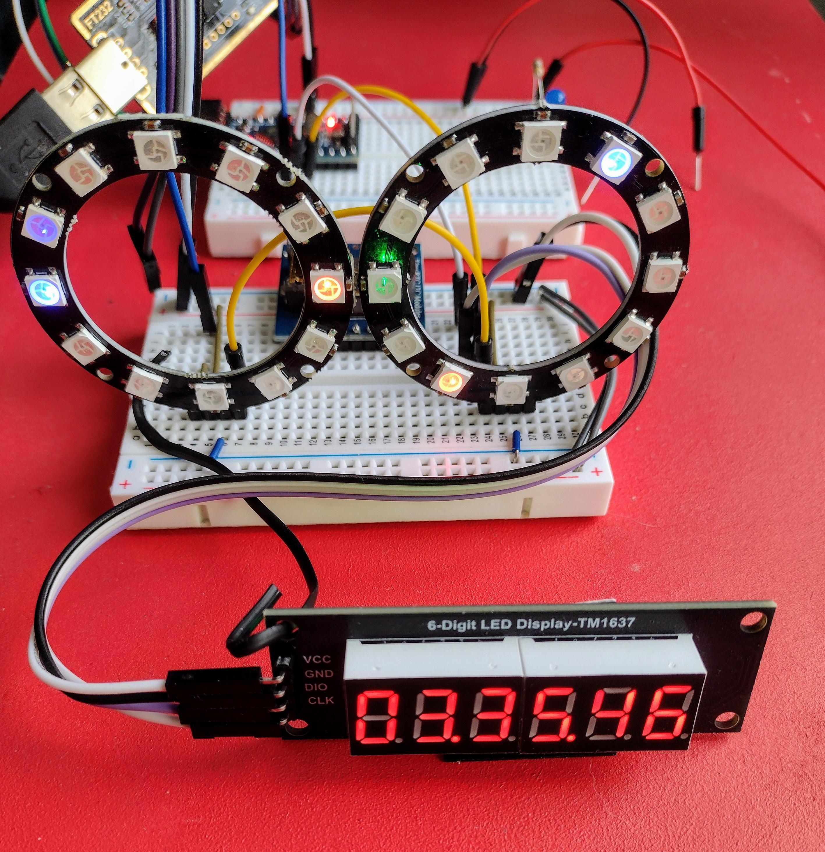
The LED rings are collections of WS2812 or compatible 5050 (i.e. 5mm square) multi-colour addressable LEDs. Adafruit call these “NeoPixels” and have a very comprehensive guide for using them here: https://learn.adafruit.com/adafruit-neopixel-uberguide
The rings that I have, have two sets of three solder pads on the rear. Both sets have VCC and GND, but one is a signal IN and one is a signal OUT. This allows them to be chained together as shown above. Two rings are required for a single dual-face unit. Some rings might have pads, holes or even connectors.
The Adafruit Uberguide talks in detail about powering these rings, especially when used in long strings for large displays. As a general rule, the recommendation is to allow for 20mA per “pixel” up to a maximum of 60mA for full brightness with all LEDS on per “pixel”.
As the Arduino can support up to 800mA via its 5V pin and I’m planning on using 8 display faces, each with 5 LEDs per face, that gives an estimate of:
- 8 x 5 x 20mA = 800 mA as a typical draw.
- 8 x 5 x 60mA = 2.4A peak for full brightness, all LEDs.
I think I can just about get away with driving my 8 faces from a Nano as long as I’m not expecting to turn everything on at full brightness – more on that in a moment when I get to the example code.
If I wanted to support something nearer the peak current I would need a separate power supply providing 5V and around 2A to the LEDs. That could probably be wired to provide a 5V link directly into the Arduino’s 5V pin too. However, this is not recommended though due to the potential for mistakes, noisy signals, and interrupts in supply, as this bypasses the regulator and any protection circuits on the Arduino.
But if I’m careful, it will be fine as an option for me if I need it.
The Code
Driving WS2812 LEDs is pretty straight forward thanks to the Adafruit_NeoPixel library for Arduino which is easily installed via the Library Manager.
One complication I have is that I need to translate between the order and number of LEDs on the rings and the 5 LEDs per ring I want to be using.
The ordering of my LEDs is as follows:
But that might be different for different rings of course. The following code is a simple test to illuminate each LED in turn allowing me to find the order, and shows all the key principles of how to turn the pixels on or off:
#include <Adafruit_NeoPixel.h>

#define LED_PIN   6
#define LED_COUNT 14

Adafruit_NeoPixel strip(LED_COUNT, LED_PIN, NEO_GRB + NEO_KHZ800);

void clearStrip () {
  for(int i=0; i<strip.numPixels(); i++) {
    strip.setPixelColor(i, strip.Color(0, 0, 0));
  }
}

void setup() {
  strip.begin();
  strip.show();
  strip.setBrightness(50);
}

void loop() {
  for(int i=0; i<strip.numPixels(); i++) {
    clearStrip();
    strip.setPixelColor(i, strip.Color(80, 35, 0));
    strip.show();
    delay(500);
  }
}
The definitions used in the Adafruit_NeoPixel initialisation (NEO_GRB+NEO_KHZ800) work for my rings, but there are several options. Try some of the library examples and consult the Uberguide for details if the rings aren’t working.
In order to map this order over to just the LEDs I need to use for my Krell display, I need two “lists” of LEDs – the real one representing the physical order the 7 LEDs per ring appear on the rings themselves, especially when linked together; and a virtual one representing the desired order of the 5 LEDs per ring I’m interested in using.
I do that via the following definitions and code:
#define LED_PIN   6
#define LED_BLOCK 5
#define LED_RINGS 8
#define LED_COUNT (LED_BLOCK*LED_RINGS)
#define STRIP_BLOCK 7
#define STRIP_COUNT (LED_RINGS*STRIP_BLOCK)

int ledpattern[LED_BLOCK] = {1,0,5,4,3};
int leds[LED_COUNT];

void setup() {
  for (int i=0; i<LED_RINGS; i++) {
    for (int j=0; j<LED_BLOCK; j++) {
      leds[LED_BLOCK*i + j] = ledpattern[j] + STRIP_BLOCK*i;
    }
  }
  ...
}
The ledpattern[] array lists which physical LED corresponds to my five virtual LEDs. The leds[] array will expand this list to the number of rings, giving offsets for all physical LEDs used to map onto all my virtual LEDs.
In order to allow this to be changed to match the number of rings used, simply by changing the #defines at the top of the code, leds[] is initialised in code as part of setup(). For two rings in a twin display, this maps virtual LEDS 0 to 9 onto real LEDS 0 to 13, with four of them being unused. For four rings in a quad display, this will map 0 to 19 onto 0 to 27, and so on.
In order to use this with the Adafruit functions, I just take my virtual LED number and use that as an index into leds[] to get the real LED number, for example:
  for(int i=0; i<LED_COUNT; i++) {
    clearStrip();
    strip.setPixelColor(leds[i], strip.Color(80, 35, 0));
    strip.show();
    delay(200);
  }
I have some example code to test all LEDs. The simple version just illuminates each LED in turn, using the above code. An alternative version will read a potentiometer and use that to determine how many LEDs to illuminate.
With the correct wiring sequence and pattern of LEDs it is possible to mimic the order of the illumination of the panels in the original film.
A note on colour, brightness and power.
As previously discussed, I’m working on the basis that not all LEDs will be on at full brightness and so can get away with powering my display simply from an Arduino. For this to be true, I’m working with the following constraints:
- No more than 8 rings are used. In my case that is two dual displays and one quad display.
- Not all LEDs are used for the colours. I’m using: strip.Color(80, 35, 0) which leaves on LED of each of the three in each pixel off and gives a nice, nostalgic, colouring which to my mind matches that used in the film quite well.
- Brightness is set relatively low, using: strip.setBrightness(50), which is less than a quarter brightness (the maximum is 255).
Find the test code on GitHub here.
Closing Thoughts
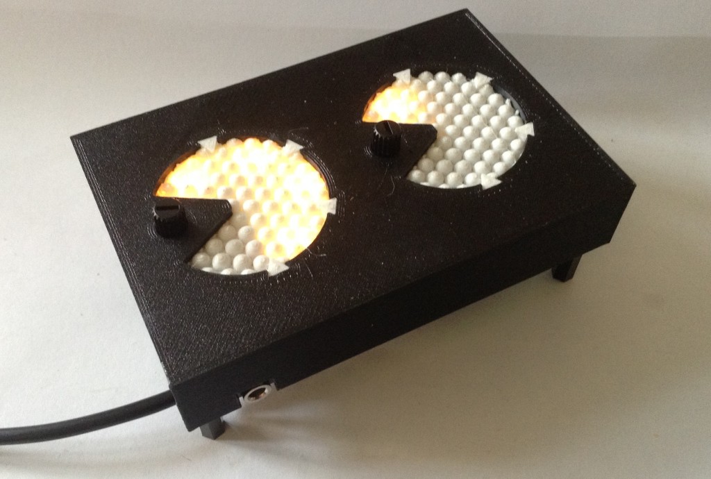
I’m really pleased with how this has turned out. It took a little trial and error to get the parts to fit and work, but the colouring through the white PLA is quite pleasing to me. The partitions also work well to allow individual control of the segments without the light bleeding through.
The simple code with a potentiometer control shows the potential. I have a few ideas for how to use this with MIDI, but those can come in a future post.
Kevin
#arduino #ForbiddenPlanet #Krell #NeoPixel