#Waveshare

2025-05-09

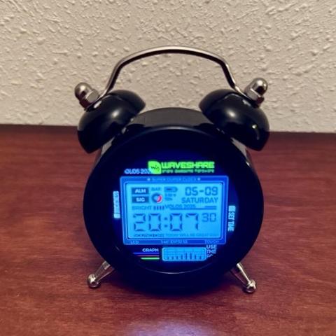
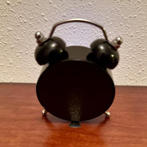
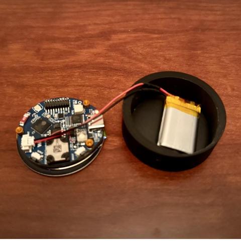
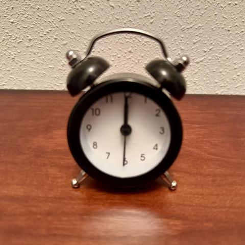
Ví en el canal de YouTube de volosprojects este proyecto (reloj analógico a digital) que acabo de emular… yo a mayores le he creado una pieza en 3d que me sirve de sujeción de la placa #waveshare 1.46 Touch LCD y de cierre del reloj lo que le da solvencia y me gusta el acabado!! #3dprinting

2025-04-16

Saw this project on #Instructables from #Moononournation instructables.com/IoT-Emoji-Si
It's a fun project, but I was more interested in the 8x8 #Neopixel #Matrix
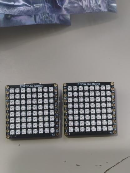
So I bought a couple of the #Waveshare #ESP32S3 8x8 boards, and printed out a couple of cases.
The boards work really well - I had an idea in mind when I ordered them, but now I forgot what I wanted to do with them.... I guess I'll make an #emjoi #display after all..... LOL

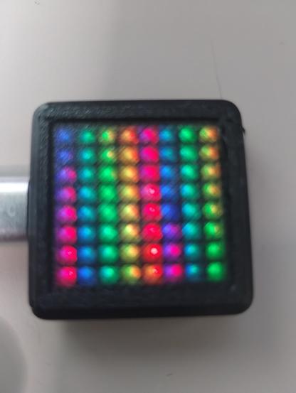
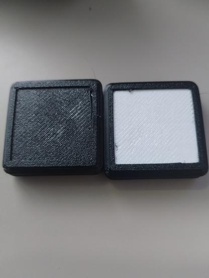
a couple of Waveshare ESP32S3 8x8 Matrix boards without casesa Waveshare 8x8 ESP32S3 Matrix in a black case with a black defuser....works pretty well under a black defuser - but I really had to bump the brightness of the neopixels up to really see the effects.  This is running the fastLED Demo100 program2 Waveshare 8x8 Matrix boards within 3d printed black cases, one with a black defuser and one with a white defuser. Not on, or displaying anything.  
The white defuser (personally) I think works better then the black, and I can lower the brightness of the leds and it still looks very bright.
2025-04-13

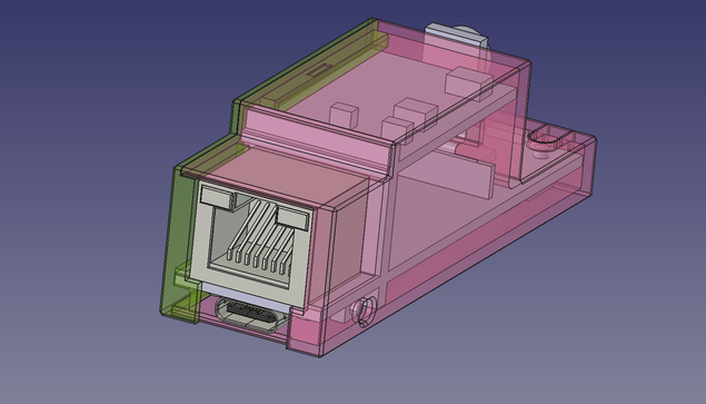
When a #PCB board designer, manufacturer and seller offers a #3D file of a board and all its measurements are off grid from the real one... 🙄

I'm looking at #Waveshare!
What do you think how I should design a fitting case for it? Tons of test prints and wasted filament? Damn... 😤

Daniele Verducci 🧉penguin86@social.ichibi.eu
2025-04-13
So, I made a #pr on #esphome #git #repository to add support to the #waveshare 7,5 inch BWR #epaper display, now let's wait for a review: https://github.com/esphome/esphome/pull/8556/commits/740253762d5c4d79920f5838bd083af435cbb764
I never contributed to esphome, nor to a C project, nor to an #embedded project in general, so I hope my #code is adequate, but I would not be surprised if I need to change something...
Let's see!
Daniele Verducci 🧉penguin86@social.ichibi.eu
2025-04-13
The original driver allocates a #framebuffer containing a single bit per pixel (that's why you can see some bitshifts in the code above). To support two colours, I need double the space. Fortunately there's already support for #BWR #eink displays in the #esphome #waveshare library, so I just need to extend WaveshareEPaperBWR instead of WaveshareEPaper and my framebuffer is magically double the size: the first half is for the black colour (as before), the second is for the red colour.
[continues...]
Daniele Verducci 🧉penguin86@social.ichibi.eu
2025-04-13
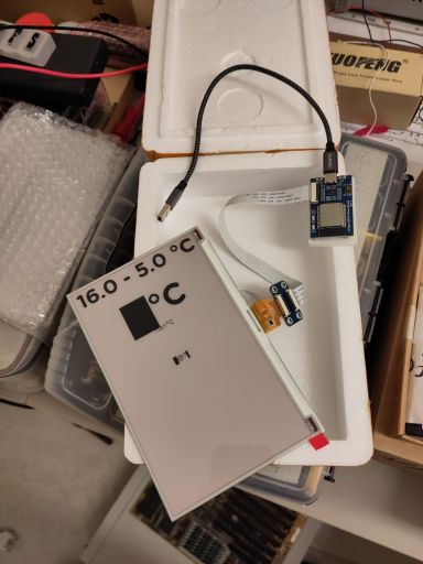
So, here's my last #rabbithole : I bought an #epaper display to use with #esphome . It's a cheap #waveshare compatible 3 colour #e-ink (BWR, black white and red), the HINK-E075A01. Unfortunately I discovered that the esphome waveshare component supports only the B/W verson.
It works in black&white, but my #display is very slow due to the added red colour, and anyway I hate leaving features on the table...
So I decided to develop a driver, for an OS I barely know (esphome), in a language I barely know (C), for a platform I barely know (ESP32). I expected it to be fun 😅
[continues]
in_sympathyin_sympathy
2025-04-07

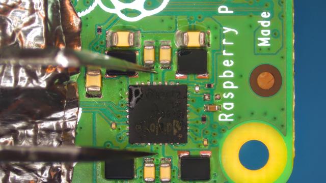
Something a bit different - a Pi with a CM4-NANO-B carrier board by .

Customer accidentally put this assembly on a metal surface and it did got shorted.

DA9090 PMIC was dead and had been replaced, but it took me quite while to figure out how to make it work again - see the thing is that when you flick the switch on a baseboard CM4 won't turn on. You have to power the whole thing down, flick the switch to ON then then power it 🤦🏻‍♂️.

diyelectromusicdiyelectromusic
2025-04-06

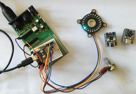
Revisiting my Duppa LED Rings this time using Waveshare Zero format devices to support USB MIDI CC controllers.

diyelectromusic.com/2025/04/06


Photo of a mini solderless breadboard with a Waveshare Zero format RP2040 board connected to a potentiometer and an I2C LED ring.  It is also connected to the MIDI interface part of a previous PCB of mine.
2025-04-03
Simple DIY Electronic Music Projectsdiyelectromusic.com@diyelectromusic.com
2025-03-30

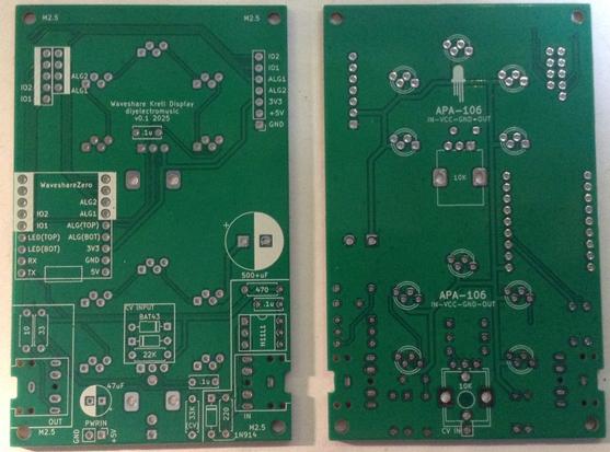
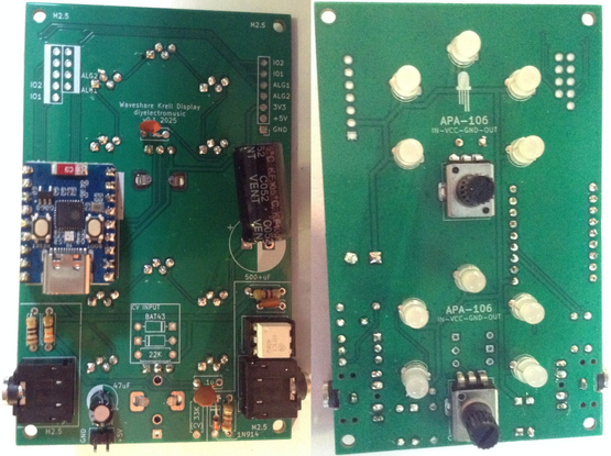
Forbidden Planet “Krell” Display PCB Build Guide

Here are the build notes for my Forbidden Planet “Krell” Display PCB. This post just looks at building the PCB for standalone use.

Further posts will explore other uses for this PCB:

Warning! I strongly recommend using old or second hand equipment for your experiments.  I am not responsible for any damage to expensive instruments!

If you are new to microcontrollers and electronics, see the Getting Started pages.

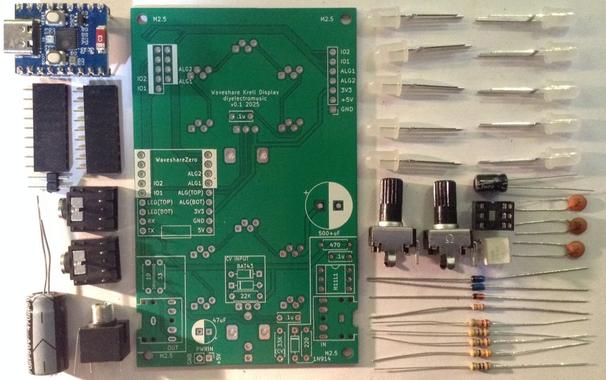
Bill of Materials

  • Forbidden Planet “Krell” Display PCB (GitHub link below)
  • Waveshare Zero format board (more here).
  • 10x APA-106 through-hole programmable RGB LEDs pinout: IN-VCC-GND-OUT.
  • 1x 500uF electrolytic capacitor (or thereabouts).
  • 1x 47uF electrolytic capacitor.
  • Optional: 2x 9-way header sockets (full or low-profile – see notes).
  • Pin headers

For the MIDI circuit:

  • 1x H11L1 optoisolator.
  • 1x 1N4148 or 1N914 signal diode.
  • Resistors: 1×10Ω, 1×33Ω, 1×220Ω, 1×470Ω.
  • 1x 100nF ceramic capacitor.
  • 2x 3.5mm stereo TRS sockets – pcb mount (see photo and PCB for footprint).
  • Optional: 1x 6-way DIP socket.

For potentiometer circuit:

  • 1 or 2 x 10K pcb-mount potentiometer (see photo and PCB for footprint).
  • 1 or 2x 100nF ceramic capactiors.

For the CV input:

  • 1x Thonkiconn style mono PCB mount jack socket.
  • Resistors: 1x22K, 1x33K.
  • 2x BAT43 Schottky diodes.

Build Steps

This posts describes a standalone module with two potentiometer controls and a MIDI circuit. For a EuroRack-style module with CV inputs refer to: Forbidden Planet “Krell” Display EuroRack Module.

Taking a typical “low to high” soldering approach, this is the suggested order of assembly:

  • All diodes and resistors.
  • DIP socket (if used) and TRS sockets.
  • Disc capacitors.
  • LEDs on rear of the board.
  • 9-way headers (if used).
  • Additional pin headers (if used).
  • Electrolytic capacitors.
  • Potentiometers on rear of the board.

Here are some build photos.

When it comes to adding the LEDs it is critical to get them in the correct pin order. These boards are designed for LEDs with two long and two shorter legs, with the pins in the order:

  • Short: IN
  • Short: VCC
  • Long: GND
  • Long: OUT

The pins need to be slightly bent to fit in the staggered footprint which means it isn’t possible to push the LEDs flush with the PCB. It is worth taking a little care to get them all to approximately the same height and vertically aligned.

Hopefully it goes without saying to be careful of rubbing the hot soldering iron tip on any of the existing plastic components.

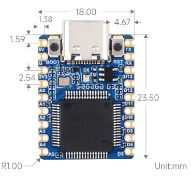
As the footprint for the Waveshare Zero is 2.54mm too wide, it is advantageous to use a Waveshare Zero format board to help angle-in the pin headers prior to soldering.

If using full height headers there will probably be enough flex to do this afterwards. If using low-profile headers then it will be necessary to get the angle correct prior to soldering.

In the following note how the large capacitor has been bent over to lie flat.

Also, I didn’t have a 500uF or higher, so used a 470uF in a 10mm diameter package.

Testing

I recommend performing the general tests described here: PCBs.

Here is some test CircuitPython code that will check the functionality of the board with a Waveshare Zero type device. This was used with a Pimoroni Tiny2040 (which has two less pins to the Waveshare Zero devices).

Analog Input

This tests the potentiometers:

import time
import board
from analogio import AnalogIn

analog_in1 = AnalogIn(board.A2)
analog_in2 = AnalogIn(board.A3)

while True:
print(analog_in1.value,"\t",analog_in2.value)
time.sleep(0.1)

On turning each of the potentiometers a value between 0 and 65536 should be printed to the serial console. Note: Mine never seems to get below 256…

LEDs

This can be used to test the LEDs. Requires the following libraries from the Adafruit Circuitpython Library Bundle:

  • neopixel.mpy
  • adafruit_pioasm.mpy (presumably only required on RP2040 based boards)
  • adafruit_pixelbuf.mpy
import time
import board
import neopixel

pixel_pin1 = board.GP2
pixel_pin2 = board.GP3
num_pixels = 5

pixels1 = neopixel.NeoPixel(pixel_pin1, num_pixels, brightness=0.3, auto_write=False, pixel_order=neopixel.RGB)
pixels2 = neopixel.NeoPixel(pixel_pin2, num_pixels, brightness=0.3, auto_write=False, pixel_order=neopixel.RGB)

while True:
for col in [(255,0,0),(0,255,0),(0,0,255),(0,0,0)]:
for pix in range(5):
pixels1[pix] = col
pixels1.show()
time.sleep(0.5)

pixels2[pix] = col
pixels2.show()
time.sleep(0.5)

time.sleep(3)

This will light each LED in turn alternating between the upper and lower sets of LEDs and then leave them off for three seconds.

MIDI IN and OUT

This requires the Adafruit MIDI library, which requires the following directory from the Adafruit Circuitpython Library Bundle:

  • adafruit_midi/*
import board
import digitalio
import busio
import adafruit_midi
from adafruit_midi.note_off import NoteOff
from adafruit_midi.note_on import NoteOn

uart = busio.UART(tx=board.GP0, rx=board.GP1, baudrate=31250, timeout=0.001)
midi = adafruit_midi.MIDI(midi_in=uart, midi_out=uart)

while True:
msg = midi.receive()
if (msg is not None):
if (isinstance(msg, NoteOn)):
print (msg)
print ("Note On: \t",msg.note,"\t",msg.velocity)
midi.send(msg)
if (isinstance(msg, NoteOff)):
print ("Note Off:\t",msg.note,"\t",msg.velocity)
midi.send(msg)

This will print out any received NoteOn and NoteOff messages (and only those) on the MIDI IN port and send them back out over the MIDI OUT port.

PCB Errata

There are the following issues with this PCB:

  •  The aforementioned Waveshare Zero footprint error.

Enhancements:

  •  It might have been useful to position the Waveshare board so that the USB connector could be presented to the edge of the board and thus left exposed when used with a case.

Find it on GitHub here.

Closing Thoughts

That is the basics of the board covered. Next will be a discussion of the alternative EuroRack supporting configuration and the physical builds for both versions.

Kevin

#APA106 #Krell #midi #pcb #waveshare
2025-03-22

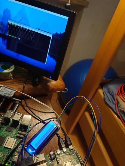
The pi I was using recognises an #i2c display from #waveshare but the i2c from the #ups hat E #upshat_e is not seen.

diyelectromusicdiyelectromusic
2025-03-14

The design and build notes are up for this regardless.

I've uploaded a fixed version of the gerber files, but actually these slightly wonky ones will be fine for most of my own messing about.

diyelectromusic.com/2025/03/14

Simple DIY Electronic Music Projectsdiyelectromusic.com@diyelectromusic.com
2025-03-14

Waveshare Zero MIDI Proto PCB Design

In the spirit of several of the other microconroller prototyping MIDI boards I’ve already made, this is one for Waveshare Zero format boards.

Warning! I strongly recommend using old or second hand equipment for your experiments.  I am not responsible for any damage to expensive instruments!

If you are new to microcontrollers, see the Getting Started pages.

The Circuit

This is essentially a 3V3 MIDI IN/OUT circuit, a 7805 based power supply and headers for the prototyping area and the Waveshare Zero format board itself. I’ve included a solder jumper to allow the bypassing of the regulator if a 5V barrel supply is used instead (this can only be used if no regulator is fitted however).

The Waveshare Zero boards can be powered via 5V directly into the 5V pin.

The only pins on the Waveshare that are connected are the power, GND and RX/TX, as these tend to all be in the same place on these boards (more here: Waveshare Zero, Pimoroni Tiny, and Neopixels). All other pins find their way to headers.

PCB Design

This follows the format of my Nano MIDI Proto PCB Design and my XIAO MIDI Proto PCB.

There are a number of additional breakout header sections for the Waveshare Zero IO pins, plus 5V, 3V3, and GND.

All the power related circuitry is together near the top of the board. It includes a 5V header and an option for direct 5V via the barrel jack, if the regulator is left out. It also includes a 3-pin 2.54mm pitch header which can be used for a power switch for the barrel jack connection.

There are overlapping footprints for MIDI DIN and TRS, so either can be populated.

Closing Thoughts

Annoyingly there were two mistakes in the first version of this PCB:

  • The TRS sockets didn’t line up properly over the MIDI sockets.
  • The header sockets for the Waveshare Zero were 2.54mm too far apartt.

Both of these could be worked around (mostly), but these issues were fixed in the above versions of the board.

Kevin

#midi #pcb #waveshare #WaveshareZero
2025-03-13

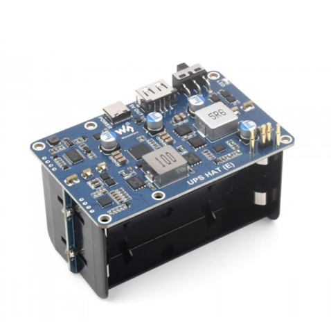
Has anyone managed to make the #waveshare #ups #hat E work on a #raspberrypi4 ? I have no #i2c data from it at all. Pins look connected. Pi has power over the pins. But no i2c.
waveshare.com/wiki/UPS_HAT_(E)
Soldered pins also do not work. i2c does not work for protected and unprotected batteries.

2025-03-12

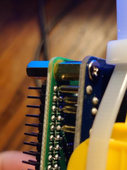
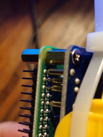
#i2c #pogopins connection of #waveshare #ups E (waveshare.com/wiki/UPS_HAT_(E)) #hat to #raspberrypi4 #gpio appears not to be detected. Anyone have similar problems with #pogopins or are they 99% reliable normally? Thanks

closeup of pogopins connect to pi 4 gpio pins
Simple DIY Electronic Music Projectsdiyelectromusic.com@diyelectromusic.com
2025-02-22

Waveshare RP2040 Matrix MIDI Monitor

Following on from my ESP32C3 OLED Mini MIDI Montor and Waveshare Zero, Pimoroni Tiny, and Neopixels this project uses a Waveshare RP2040 mini Matrix display. This is largely the same pinout as the other Waveshare boards, but includes a 5×5 programmable LED (i.e. neopixel-like) matrix.

https://makertube.net/w/cdxAJJvsqsPKrzVg6xWodD

Warning! I strongly recommend using old or second hand equipment for your experiments.  I am not responsible for any damage to expensive instruments!

If you are new to microconrtollers, see the Getting Started pages.

Parts list

  • Waveshare RP2040 Matrix
  • Optional: MIDI interface
  • Optional: Breadboard and jumper wires

The Circuit

If used with USB MIDI, then all that is required is to plug the RP2040 Matrix into a computer and it will be able to come up as a USB MIDI device called “CircuitPython Audio”.

If serial MIDI is required, then a Ready-Made MIDI Module supporting 3V3 operation is needed and can be connected to TX/RX on GPIO 0 and GPIO 1 as well as 3V3 and GND.

The Code

I’m using Circuitpython for this one. It uses the same version of Circuitpython as the Waveshare RP2040 Zero – details here. It requires the following libraries to be installed:

  • /lib/adafruit_midi/*
  • /lib/neopixel
  • /lib/adafruit_pixelbuf

The string of Neopixels is hooked up to GPIO16, so can be initialised as follows:

pixel_pin = board.GP16
num_pixels = 25

pixels = neopixel.NeoPixel(pixel_pin, num_pixels, brightness=0.1, auto_write=False, pixel_order=neopixel.RGB)

I’m using the Adafruit MIDI library to pull out NoteOn and NoteOff events and using those to set certain LEDs.

The code can run off USB MIDI or serial MIDI:

# Serial MIDI
uart = busio.UART(tx=board.TX, rx=board.RX, baudrate=31250, timeout=0.001)
midi = adafruit_midi.MIDI(midi_in=uart)

--------

# USB MIDI
midi = adafruit_midi.MIDI(midi_in=usb_midi.ports[0])

As there are only 25 LEDs I set a range of MIDI notes to respond to at the start.

MIN_NOTE=48       # MIDI Note C3
MAX_NOTE=(48+25-1) # MIDI Note C#5

The main loop just cycles around checking for MIDI events and updating the LEDs.

while True:
msg = midi.receive()
if (msg is not None):
if (isinstance(msg, NoteOn)):
if (msg.note >= MIN_NOTE and msg.note <= MAX_NOTE):
pixels[midi2pix(msg.note)] = GREEN;

if (isinstance(msg, NoteOff)):
if (msg.note >= MIN_NOTE and msg.note <= MAX_NOTE):
pixels[midi2pix(msg.note)] = OFF;

pixels.show()

The Neopixel strip is scanned and MIDI is checked every time through the loop, but the display only changes if a NoteOn or NoteOff is received.

In terms of mapping notes to the LEDs, I’m keeping it simple and just using the LEDS in the string order they are already arranged.

This does however mean one compromise – I either go top-left to bottom-right; or bottom-right to top-left. That is because of the ordering of the matrix. There is more here: https://thepihut.com/blogs/raspberry-pi-tutorials/coding-the-waveshare-rp2040-matrix

Ideally, I’d go bottom-left to top-right, but that would mean some fancier mapping of position to note that I’m not bothered about doing at this stage.

Find it on GitHub here.

Closing Thoughts

At some point I’ll be able to resist a neat, small display, but today is not that day. And it is doubly hard when it is a small LED matrix.

This is a fun little board and I’m chewing over a few other ideas now I’ve got the basics out of the way.

Kevin

#circuitpython #ledMatrix #midi #rp2040 #waveshare

Client Info

Server: https://mastodon.social
Version: 2025.04
Repository: https://github.com/cyevgeniy/lmst